
System and method for switch mode power supply delay compensation

a delay compensation and switch mode technology, applied in the field of power supply compensation, can solve the problems of difficulty in coordinating the insertion of dead time in switching events, and the problem of efficiency problems, and achieve the effect of avoiding oscillation

Active Publication Date: 2010-01-07
TEXAS INSTR INC
View PDF5 Cites 8 Cited by
  • Summary
  • Abstract
  • Description
  • Claims
  • Application Information

AI Technical Summary

Benefits of technology

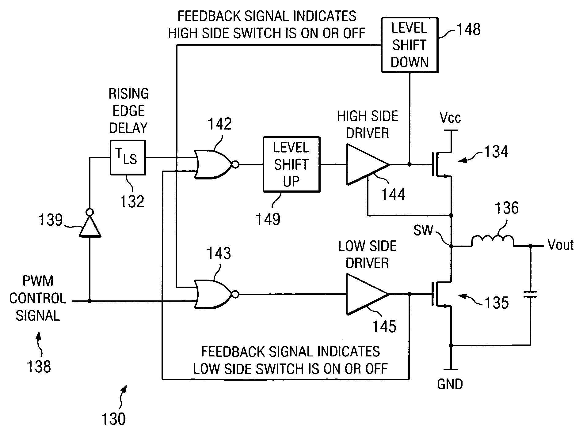
[0010]The disclosed system and method provide a compensation for a switch mode power converter to avoid oscillation between continuous conduction and discontinuous conduction modes. According to one exemplary embodiment, a delay element is provided to delay high side switch turn-on in a PWM controlled switch mode power converter. The delay element for turning on a high side switch maintains operation in discontinuous conduction mode to avoid continuous conduction operation at low current or light load conditions. According to one aspect, the delay element provides a delay approximately equal to the turn-off time for the low side switch. The delay can equal, for example, a driver propagation delay and low side switch turn-off time. Turn-on for the high side switch is inhibited for a period of time with the delay element, so that high side switch turn-on has an equalized delay with respect to operation in continuous or discontinuous conduction mode. The resulting equalized turn-on time for the high side switch avoids oscillation between discontinuous and continuous conduction modes.

Problems solved by technology

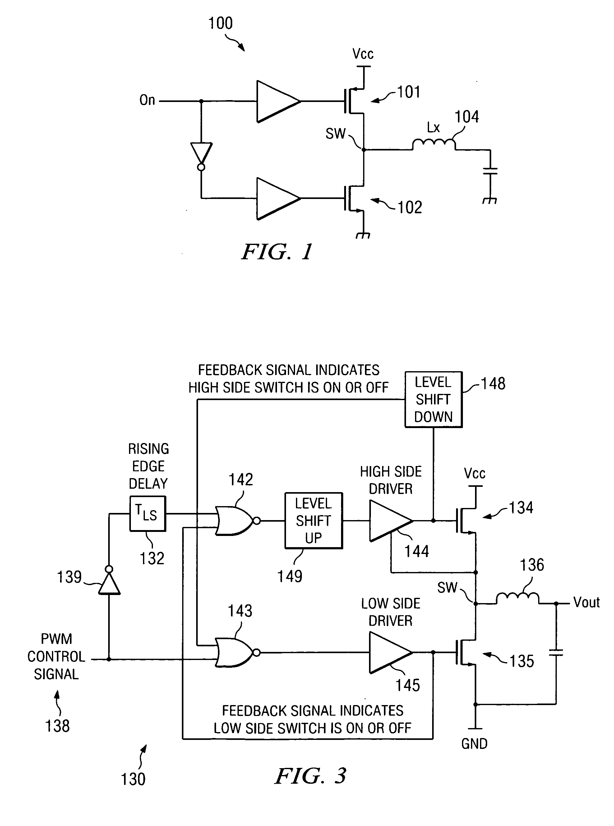
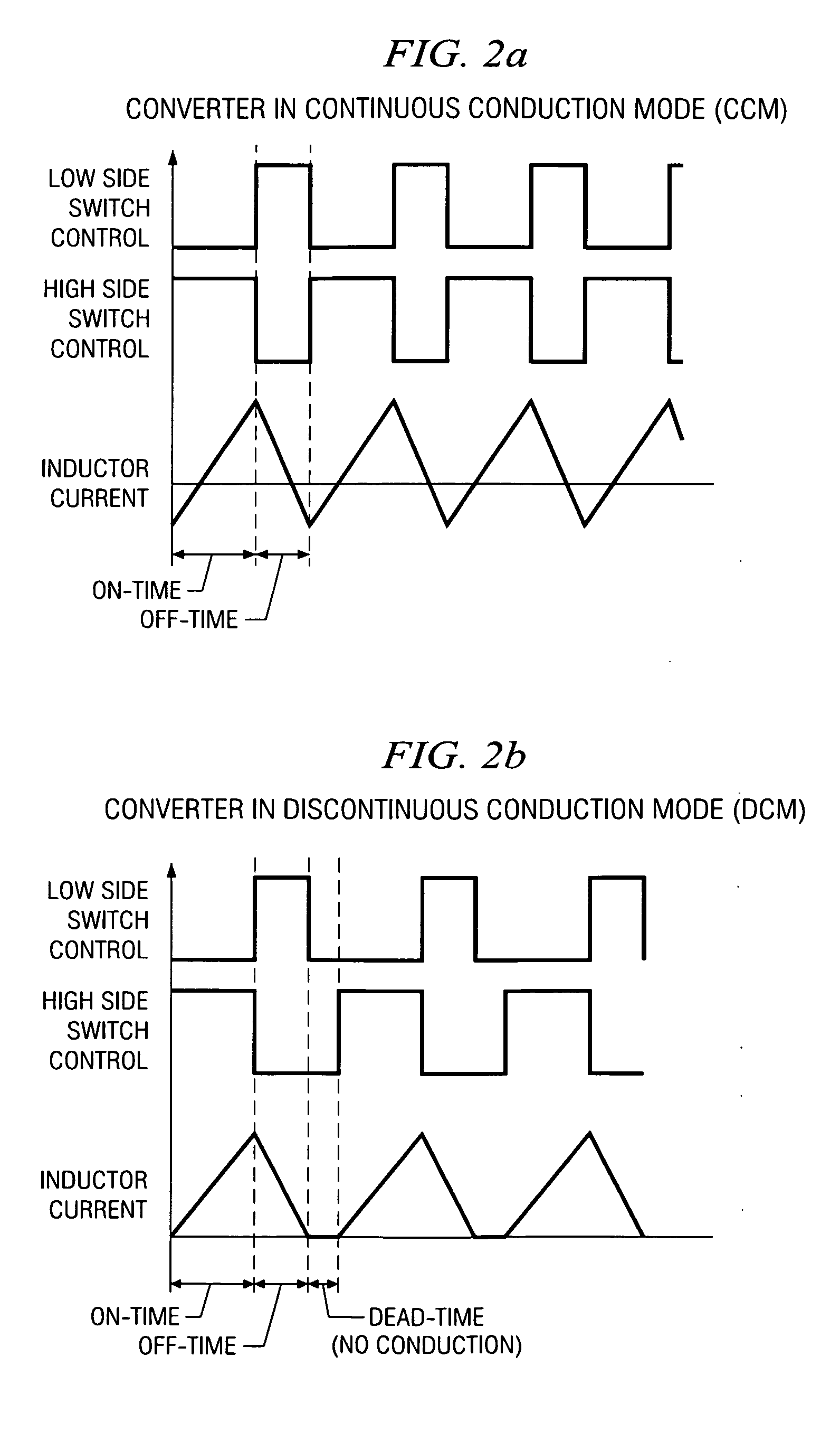
A challenge in operating power stage 100 is to switch between continuous conduction mode and discontinuous conduction mode due to transitions between heavy and light loads on the output.
It can sometimes be challenging to coordinate the insertion of dead time in switching events when power stage 100 changes from discontinuous conduction mode to continuous conduction mode, or vice versa.
A difficulty arises when power stage 100 operates in relatively light load conditions in which the mode may be continuous conduction or discontinuous conduction, depending upon the load.
This oscillation can be problematic for efficiency, component protection and input boosting, for example.

Method used


Image

  • System and method for switch mode power supply delay compensation
  • System and method for switch mode power supply delay compensation
  • System and method for switch mode power supply delay compensation

Examples


Embodiment Construction

[0016]The disclosed system and method provides a compensation for a switch mode power converter operating in discontinuous and continuous modes to avoid oscillation between operation in the different modes.

[0017]Referring now to FIG. 3, a circuit diagram 130 illustrates a control for a power stage of a switch mode power converter. Circuit 130 includes high and low side switches 134, 135 that are operated to charge and discharge inductor 136. According to an exemplary embodiment, high and low side switches 134, 135 are implemented as FETs, and in particular, MOSFETs. A PWM control signal 138 is used to drive high and low side switches 134, 135 to turn on and off in either a continuous or discontinuous conduction mode. An inverter 139 is used to prevent cross-conduction between switches 134, 135, so that one switch is off while the other switch is conducting. Drivers 144, 145 are used to drive switches 134, 135, respectively, to turn on and off in accordance with an input control sign...


PUM


Abstract

A delay applied to a turn-on time for a high side switch in a switch mode power converter prevents oscillation between continuous and discontinuous conduction modes under light load conditions. The delay equalizes turn-on time for a high side switch with respect to continuous and discontinuous modes, so that turn-on time is not treated differently between the different modes. The delay value can be set for be equivalent to a propagation delay through a driver for a low side switch, in addition to a turn-off time for the low side switch. The addition of the delay element tends to maintain the switch mode power converter in a discontinuous mode under light load conditions and avoids oscillation between discontinuous and continuous conduction modes.

Description

CROSS REFERENCE TO RELATED APPLICATIONS[0001]N / ASTATEMENT REGARDING FEDERALLY SPONSORED RESEARCH OR DEVELOPMENT[0002]N / ABACKGROUND OF THE INVENTION[0003]The present disclosure relates generally to power supply compensation, and more particularly to power supply parameter adjustment to improve light load operation.[0004]DC / DC power converters can operate in a number of different modes, including continuous, discontinuous and transition modes. In continuous mode, also referred to sometimes as synchronous mode, an inductor that is charged and discharged has a substantially continuous current waveform, and may have negative current through the inductor. In transition mode, the inductor may have a continuous current waveform, and the inductor current is nonnegative. In discontinuous mode, sometimes referred to as nonsynchronous mode, the inductor current waveform is noncontinuous and the inductor current is nonnegative. In general, a DC / DC power converter can have improved efficiency at ...

Claims


Application Information

Patent Timeline
IPC IPC(8): H02M3/335
CPCH02M3/158
Inventor BROHLIN, PAUL L.TERRY, STEPHENSTAIR, RICHARD K.
Owner TEXAS INSTR INC
Learn More