Reproduction signal evaluation method, reproduction signal evaluation unit, and optical disk device adopting the same

a reproduction signal and evaluation method technology, applied in the direction of digital signal error detection/correction, amplitude demodulation, instruments, etc., can solve the problems of generating some problems in the reproduction signal evaluation method, increasing inter-symbol interference and signal noise ratio, and high correlation with the error rate. , the effect of high accuracy

Inactive Publication Date: 2010-01-07
PANASONIC CORP +1
View PDF13 Cites 17 Cited by
  • Summary
  • Abstract
  • Description
  • Claims
  • Application Information

AI Technical Summary

Benefits of technology

[0022]According to the foregoing structure, a standard deviation, which corresponds to an error rate predicted from the mean value of the differential metrics which are not greater than the extracted signal processing threshold, is determined, and the quality of the reproduction signal is evaluated using this standard deviation. It is therefore possible to realize a signal evaluation having very high correlation with the error rate. As a result, a reproduction signal evaluation method, which is suitable for a system using a PRML signal processing system and which can evaluate the quality of reproduction signals of information recording media at high accuracy, can be implemented.

Problems solved by technology

Recently the shortest mark length of recording marks have reached the limit for optical resolution, and an increase in inter-symbol interference and deterioration of SNR (Signal Noise Ratio) are becoming obvious as the density of optical disk media increases, therefore the use of a PRML (Partial Response Maximum Likelihood) system as a signal processing method is becoming common.
On the other hand, a shift in signal processing systems from a level decision to PRML has resulted in generating some problems in reproduction signal evaluation methods.
As the density of magnetic disk media increases further, the problem of inter-symbol interference and SNR deterioration becomes more serious.
However, with the method according to Japanese Patent Application Laid-Open No. 2003-272304, the error rate cannot be predicted accurately if recording distortion occurs to recording signals.
This problem becomes particularly conspicuous when data is recorded by thermal recording, such as the case of an optical disk, since recording distortion tends to be generated by thermal interference.
As the density of optical disk increases, space between recording pits decreases even more, and an increase in thermal interference is expected, therefore this problem will be unavoidable in the future.
Generally speaking, the spread of the distribution of the differential metric is caused by the noise generated in an optical disk.
An increase in the index value should mean an increase in the probability of error generation, but errors decrease in the case of FIG. 15C.
A problem similar to the above also occurs in the case shown in FIG. 15D. FIG. 15D is a case when the determined distribution of the differential metric is not normal distribution.
Just like the case of FIG. 15C, error rate also decreases when the index value increases.
But a new problem, mentioned herein below, occurs, since a predetermined threshold is used and a number of differential metrics exceeding this threshold is measured.
This means that a wide area must be measured in order to increase the accuracy of the measurement, which increases the measurement time and diminishes measurement stability.
The method disclosed in Japanese Patent Application Laid-Open No. 2003-51163, on the other hand, does not have this advantage of the conventional method based on time axis jitter, which is not affected by the defects, and therefore has a problem when used for the index values of optical disks, which is a system where such defects as scratches and fingerprints easily occur.
In order to increase the number of differential metrics to be measured using the method according to Japanese Patent Application Laid-Open No. 2003-51163, the threshold could be increased, but if the threshold is increased, another problem occurs, that is the accuracy of the predicted error rate drops.
In this way, in the case of the method according to Japanese Patent Application Laid-Open No. 2003-51163, the value of the threshold must be adjusted in order to maintain constant measurement accuracy depending on the quality of measured signals, and such adjustment is possible if the manner of how distribution spreads is somewhat understood, nonetheless this is a major problem for optical disks, where signal quality changes significantly.
Japanese Patent Application Laid-Open No. 2003-51163 and No. 2003-272304 also disclose a method of using bER predicted by the differential metric as the index, but if this is used as an index value, compatibility with the time axis jitter, which has been used as the signal quality evaluation index of optical disks, is lost, and handling is difficult.

Method used


Image

  • Reproduction signal evaluation method, reproduction signal evaluation unit, and optical disk device adopting the same
  • Reproduction signal evaluation method, reproduction signal evaluation unit, and optical disk device adopting the same
  • Reproduction signal evaluation method, reproduction signal evaluation unit, and optical disk device adopting the same

Examples


first embodiment

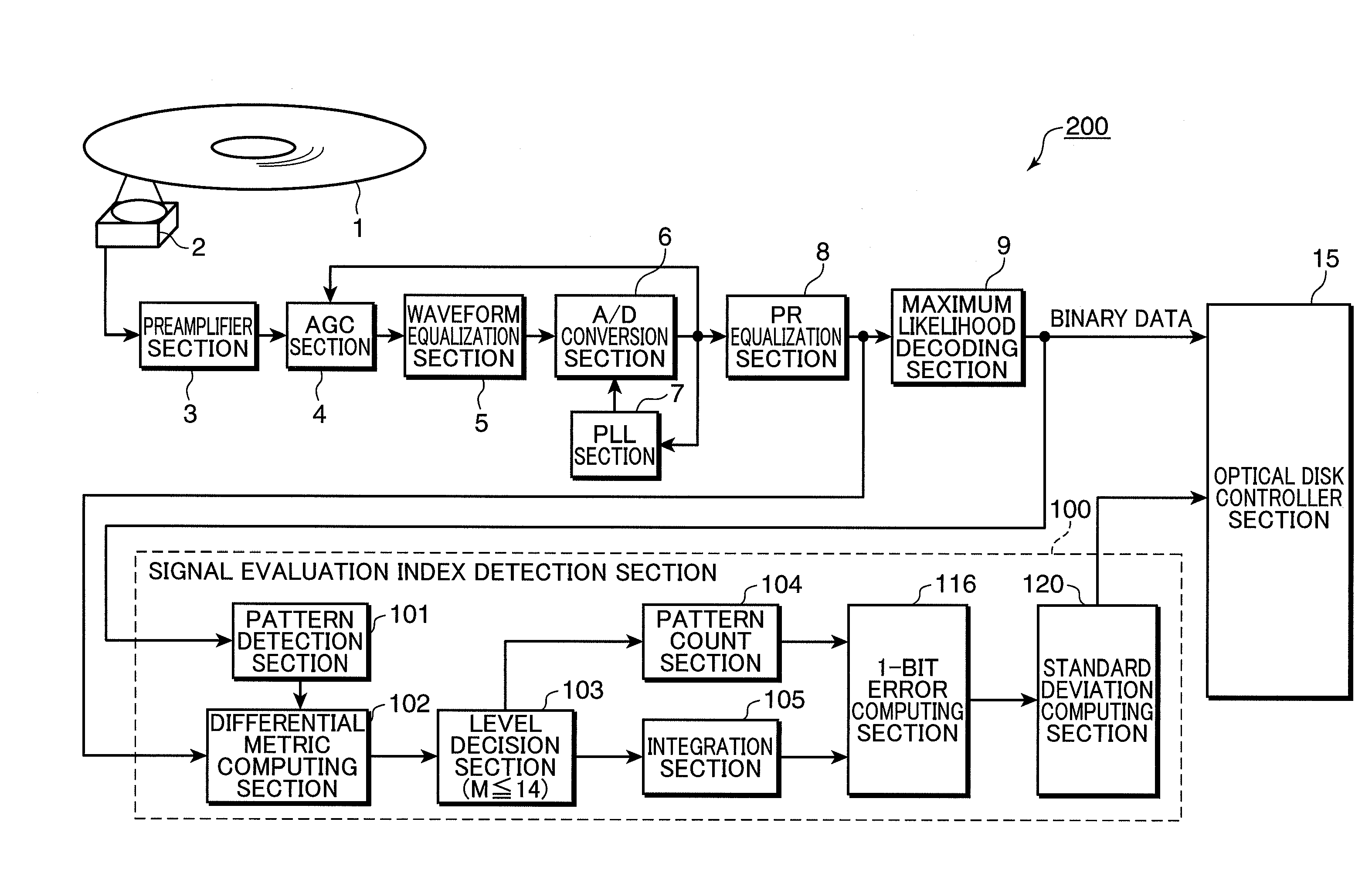
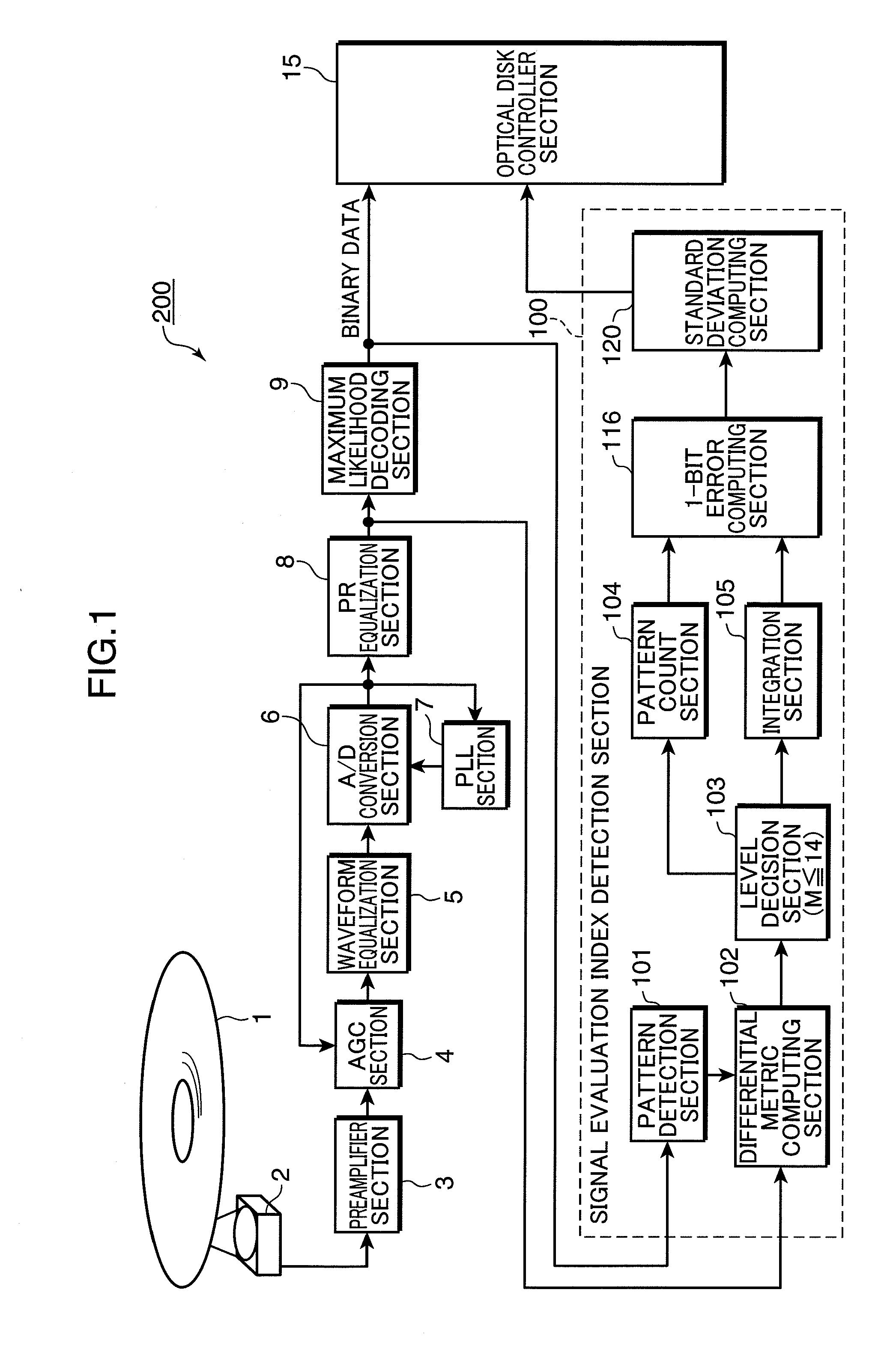
[0070]An optical disk device having a reproduction signal evaluation unit according to one embodiment of the present invention will now be described with reference to the drawings. FIG. 1 is a block diagram depicting a structure of the optical disk device 200 according to the first embodiment.

[0071]An information recording medium 1 is an information recording medium for optically recording / reproducing information, and is an optical disk medium, for example. The optical disk device 200 is a reproduction unit which reproduces information from the installed information recording medium 1.

[0072]The optical disk device 200 has an optical head section 2, a preamplifier section 3, an AGC (Automatic Gain Controller) section 4, a waveform equalization section 5, an A / D conversion section 6, a PLL (Phase Locked Loop) section 7, a PR equalization section 8, a maximum likelihood decoding section 9, a signal evaluation index detection section (reproduction signal evaluation unit) 100, and an opt...

second embodiment

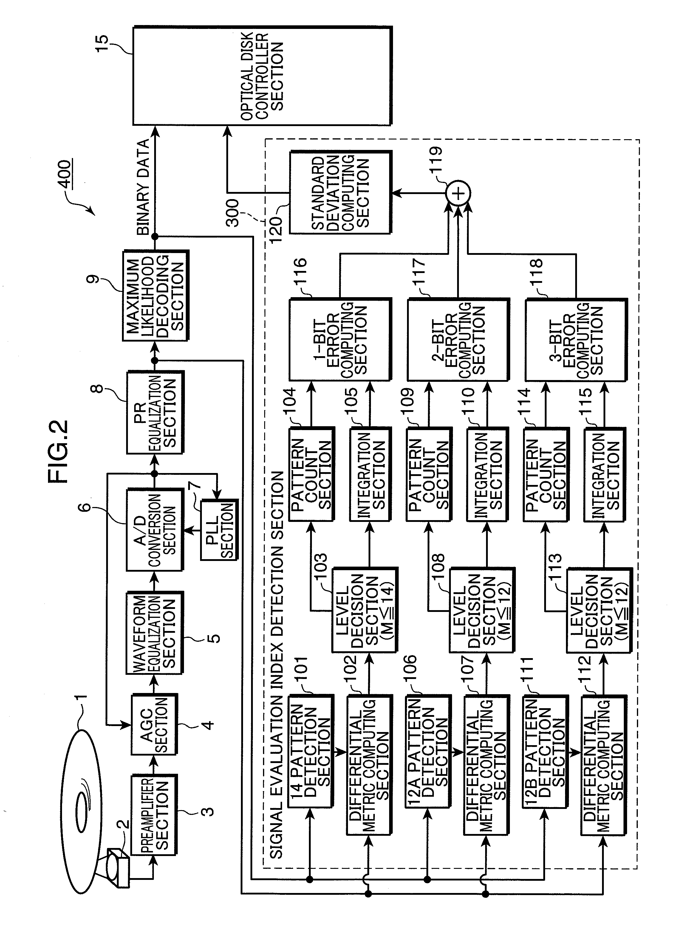
[0103]An optical disk device having a reproduction signal evaluation unit according to another embodiment of the present invention will now be described with reference to the drawings. A composing element the same as the first embodiment is denoted with a same element number, for which description can be omitted. FIG. 2 is a block diagram depicting the structure of the optical disk device 400 of second embodiment.

[0104]An information recording medium 1 is an information recording medium for optically recording / reproducing information, and is an optical disk medium, for example. The optical disk device 400 is a reproduction unit which reproduces information from the installed information recording medium 1.

[0105]The optical disk device 400 has an optical head section 2, a pre-amplifier section 3, an AGC (Automatic Gain Controller) section 4, a waveform equalization section 5, an A / D conversion section 6, a PLL (Phase Locked Loop) section 7, a PR equalization section 8, a maximum like...

third embodiment

[0138]An optical disk device according to still another embodiment of the present invention will now be described with reference to the drawings.

[0139]FIG. 13 is a block diagram depicting a general structure of the optical disk device of the present embodiment.

[0140]The optical disk device 600 has: an optical head section 2, a pre-amplifier section 3, an AGC (Automatic Gain Controller) section 4, a waveform equalization section 5, an A / D conversion section 6, a PLL (Phase Locked Loop) section 7, a PR equalization section 8, a maximum likelihood decoding section 9, a signal evaluation index detection section (reproduction signal evaluation unit) 500 and an optical disk controller section 15. The structures and functions of these composing elements constituting the optical disk device 600 are the same as the first embodiment, and descriptions thereof are omitted here.

[0141]The optical disk device 600 according to the present embodiment has a signal evaluation index detection section 5...


PUM

PropertyMeasurementUnit
diameteraaaaaaaaaa
wavelengthaaaaaaaaaa

Abstract

A reproduction signal evaluation method for evaluating quality of a reproduction signal reproduced from an information recording medium based on a binary signal generated from the reproduction signal using a PRML signal processing system, includes: a pattern extraction step of extracting, from the binary signal, a specific state transition pattern which has the possibility of causing a bit error; a step of computing a differential metric based on the binary signal; an extraction step of extracting the differential metric which is not greater than a predetermined signal processing threshold; a step of determining a mean value of the differential metrics which are not greater than the signal processing threshold and extracted in the extraction step; a standard deviation computing step of determining a standard deviation which corresponds to an error rate predicted from the mean value; and an evaluation step of evaluating a quality of the reproduction signal using the standard deviation.

Description

BACKGROUND OF THE INVENTION[0001]1. Field of the Invention[0002]The present invention relates to a reproduction signal evaluation method and reproduction signal evaluation unit using a PRML signal processing system, and an optical disk device adopting the same.[0003]2. Description of the Related Art[0004]Recently the shortest mark length of recording marks have reached the limit for optical resolution, and an increase in inter-symbol interference and deterioration of SNR (Signal Noise Ratio) are becoming obvious as the density of optical disk media increases, therefore the use of a PRML (Partial Response Maximum Likelihood) system as a signal processing method is becoming common.[0005]The PRML system is a technology combining partial response (PR) and maximum likelihood (ML) decoding, and is a known system for selecting a most likely signal sequence from a reproduced waveform, assuming the occurrence of inter-symbol interference. As a result, it is known that decoding performance im...

Claims


Application Information

Patent Timeline
Patent Type & Authority Applications(United States)
IPC IPC(8): G11B7/00
CPCG11B20/10009G11B2220/2541G11B20/10046G11B20/10055G11B20/1012G11B20/10212G11B20/10277G11B20/10296G11B20/10361G11B20/1037G11B20/10398G11B20/10425G11B20/10472G11B20/10481G11B20/1816G11B20/182G11B20/22G11B20/10027
Inventor MIYASHITA, HARUMITSUHINO, YASUMORISHIRAISHI, JUNYAKOBAYASHI, SHOEI
Owner PANASONIC CORP
Why Eureka
Try Eureka