Method for making composite abrasive compacts

a technology of composite abrasives and compacts, which is applied in the direction of manufacturing tools, grinding devices, other chemical processes, etc., can solve the problems of delamination of the ultra hard material layer from the substrate, compacting of the ultra hard layer, and delamination of etc., and achieve the effect of thinning the ultra hard material layer

Inactive Publication Date: 2010-01-14
SMITH INT INC
View PDF37 Cites 19 Cited by
  • Summary
  • Abstract
  • Description
  • Claims
  • Application Information

AI Technical Summary

Problems solved by technology

However, an increase in the thickness of the ultra hard material layer may result in delamination of the ultra hard material layer from the substrate due to residual stresses generated at the interface between the ultra hard material and the substrate.
Also, during HPHT sintering, the ultra hard layer is compacted due to pressure and due to crushing of the particles.
The increased stresses can cause delamination of the ultra hard material layer from the substrate.
As such, the maximum thickness of the sintered ultra hard material layer is limited by the magnitude of these stresses.
Additionally, the shrinkage of the ultra hard material causes a pressure drop in the pressure cell of the high pressure apparatus, which reduces the magnitude of the pressure applied by the press and hinders the HPHT sintering process.
If the amount of shrinkage is too high, the press may not be able to apply sufficient pressure to HPHT sinter the material, resulting in a weaker compact.
Furthermore, as previously discussed, due to the elastic modulus and coefficient of thermal expansion mismatch between the ultra hard material and the substrate, high residual stresses arise during the cooling down phase of the HPHT sintering process, which ultimately leads to spalling and poor performance of the ultra hard material layer.

Method used


Image

  • Method for making composite abrasive compacts
  • Method for making composite abrasive compacts
  • Method for making composite abrasive compacts

Examples


Embodiment Construction

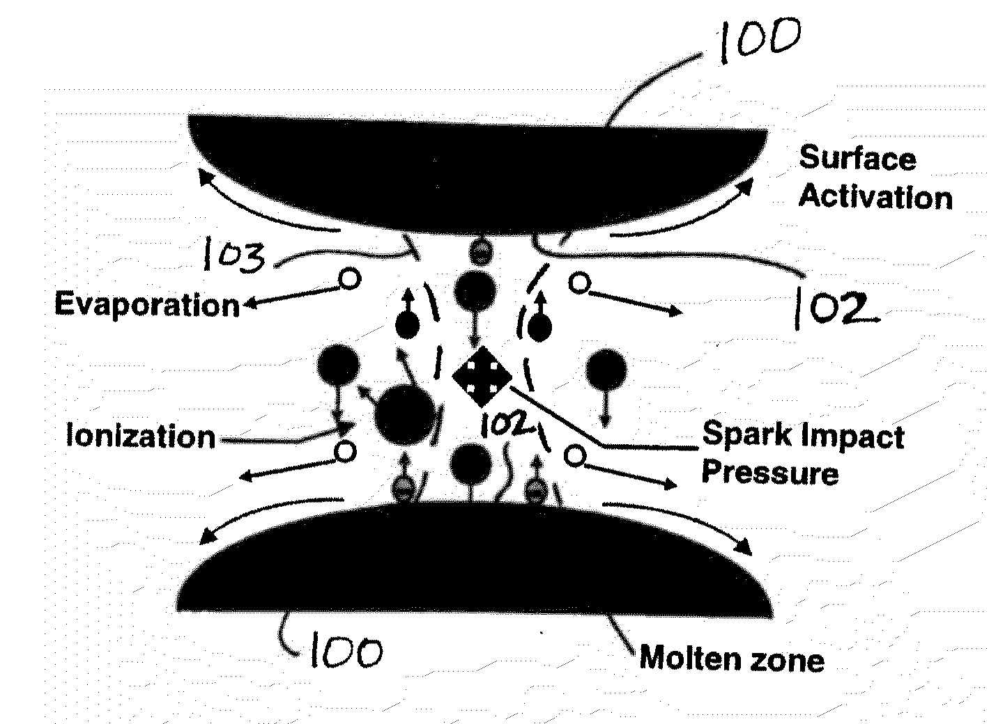
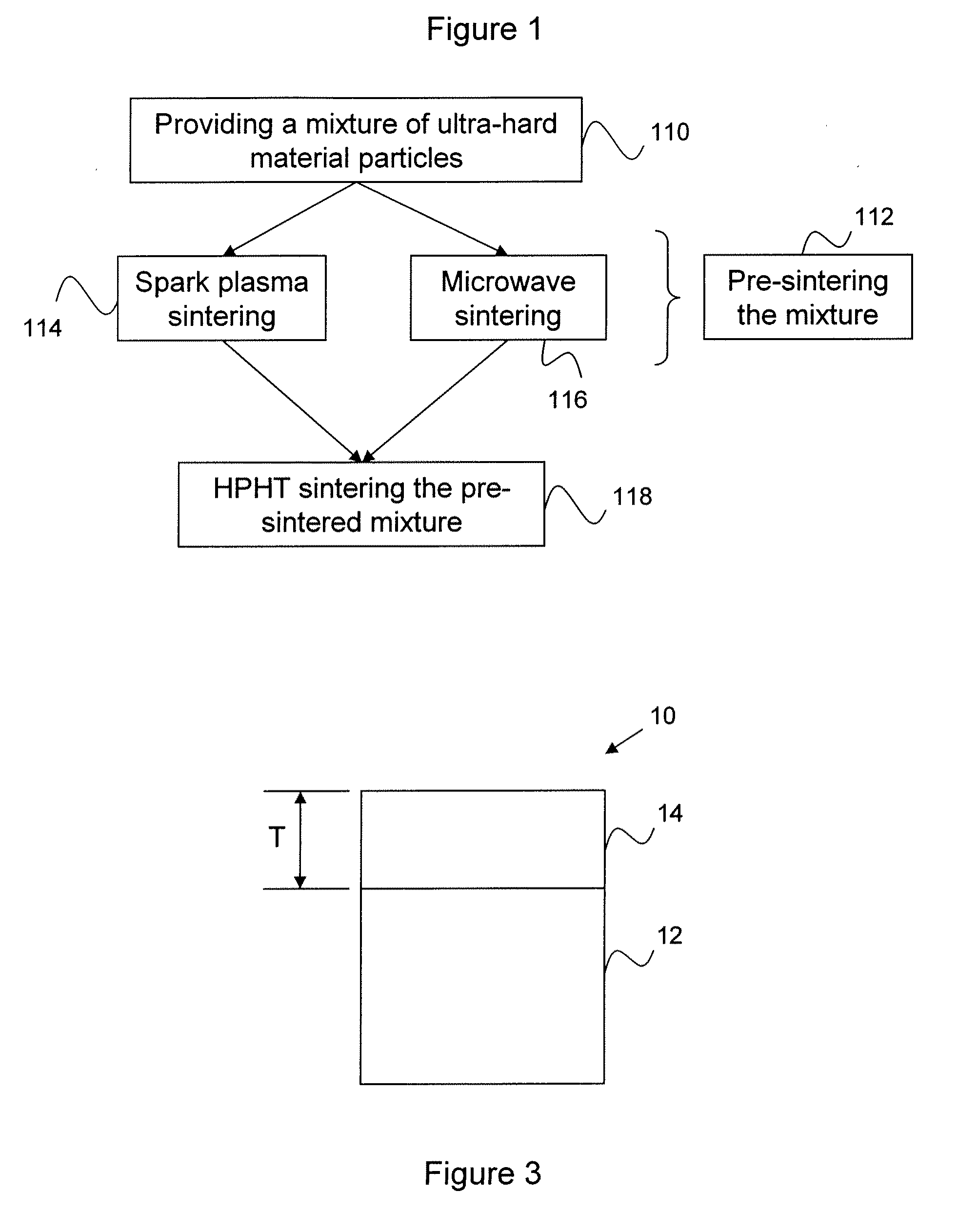
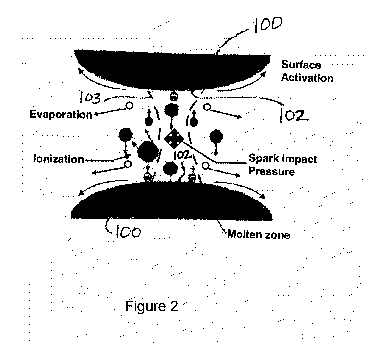
[0014]The present invention relates to polycrystalline ultra hard material cutting elements, and more particularly to a method of forming a polycrystalline ultra hard material cutting element with a thicker ultra hard layer than cutting elements formed by prior art methods. In an exemplary embodiment, such a method includes pre-sintering the ultra hard material powder to form an ultra hard material layer that is partially or fully densified prior to HPHT sintering, so that the ultra hard layer is pre-shrunk. Applicant has discovered that by pre-sintering, a thicker ultra hard material layer can be produced. This pre-sintering in an exemplary embodiment is achieved by means of a spark plasma process, or in another exemplary embodiment by a microwave sintering process.

[0015]As the volume of ultra hard material layer increases, the amount of shrinkage during sintering or pre-sintering also increases. This makes it difficult to pre-sinter large volumes of ultra hard particles in the sam...


PUM

PropertyMeasurementUnit
temperatureaaaaaaaaaa

Abstract

The present invention relates to polycrystalline ultra hard material cutting elements, and more particularly to a method of forming a polycrystalline ultra hard material cutting element with a thicker ultra hard layer than cutting elements formed by prior art methods. In an exemplary embodiment, such a method includes pre-sintering the ultra hard material powder to form an ultra hard material layer that is partially or fully densified prior to HPHT sintering, so that the ultra hard layer is pre-shrunk. This pre-sintering in an exemplary embodiment is achieved by means of a spark plasma process, or in another exemplary embodiment by a microwave sintering process.

Description

CROSS-REFERENCE TO RELATED APPLICATION[0001]This application claims the benefit of and priority to U.S. Provisional Application No. 61 / 134,373, filed on Jul. 8, 2008, the contents of which are fully incorporated herein by reference.BACKGROUND OF THE INVENTION[0002]Polycrystalline ultra hard material composite abrasive compacts such as cutting elements or shear cutters include a cutting layer such as polycrystalline diamond (“PCD”) or polycrystalline cubic boron nitride (“PCBN”) or thermally stable polycrystalline ultra hard material (“TSP”) formed over a substrate such as a cemented tungsten carbide substrate. Such compacts have well-known applications in the industry. For example, they may be mounted on a rock bit and used for oil, gas drilling and mining operations. These compacts are produced by sintering ultra hard material particles (typically provided in powder form), such as diamond or cubic boron nitride (CBN) particles, over a tungsten carbide substrate at a high pressure a...

Claims


Application Information

Patent Timeline
Patent Type & Authority Applications(United States)
IPC IPC(8): C09K3/14B01J3/06C01B21/064
CPCB01J3/062B01J2203/062B01J2203/0685B01J2203/0655B01J2203/066B01J2203/0645
Inventor BELLIN, FEDERICO
Owner SMITH INT INC
Why Eureka
Try Eureka