Aerodynamic separation nozzle

Active Publication Date: 2010-01-14
TENOROC
View PDF12 Cites 27 Cited by
  • Summary
  • Abstract
  • Description
  • Claims
  • Application Information

AI Technical Summary

Benefits of technology

[0040]Another embodiment of this device and method is to have the aerodynamic separation nozzle configured into a separation cascade arrangement where the inlet gas enters the separation cascade of successive aerodynamic separation nozzles, and is separated of some of its constituents through successive inter-cascade flows that produce a product stream and a waste stream. The operation of the various embodiments of a cascade system of separation nozzles is specified by the type of application, wherein the cascade is at least two successive stages and may be as many as 20 or more stages selected according to the separation performance of each separation nozzle stage and the desired quality of the outlet gas products. In some embodiments, the cascade system is operated from the initial pressure of the inlet gas, wherein the gas pressure of the processing gas is reduced through each stage as is specified by the separation nozzle geometry. In other embodiments, an individual stage pump is used to repressurize the gas prior to each successive separation nozzle stage. The stage pump thus recovers the pressure that is reduced in the expansion process at the prior separation nozzle stage. In other embodiments, the design of the separation nozzle stages of the cascade varies and is separately sized from the bottom to the top of the cascade thereby allowing the flow volume at each stage to be regulated by each stage's nozzle geometry to control the throughput of the gas and adapted to accommodate the residual pressure of the process gas exiting the earlier stage as an inlet to the current stage and maintain relative pressure ratios across the separation nozzle by adjusting the total volume and physical geometry of the separation nozzle.
[0041]An embodiment of the present device and method is fabricated to be a supersonic nozzle that is curved in its divergent section, whereby process gas is expanded through a nozzl

Problems solved by technology

However, oxygen concentrators capable of supplying more than 1-2 liters per minute of oxygen are typically larger, bulkier units that are not suitable for portable use and require large quantities of energy to operate.
Thus, most patients who require oxygen therapy when outside the home must use traditional liquid oxygen bottles that are heavy and potentially dangerous.
Production of these tiny nozzles by manufacturing is technically demanding, and the overall process typically includes stages having multiple vessels containing hundreds of separation elements, gas distribution manifolds, gas coolers to remove the heat of compression, and centrifugal co

Method used


Image

  • Aerodynamic separation nozzle
  • Aerodynamic separation nozzle
  • Aerodynamic separation nozzle

Examples


Example

[0179]In a second embodiment, the process gas is substantially gaseous upon impinging the separation skimmer 112, however during at least a portion of the flow along the separation flow path 130 the process gas was a two-phase flow with at least a portion of one of the constituents in a liquid phase. In this second embodiment, the liquid phase enhances the diffusion of the heavier, liquid phase constituents toward the deflection wall 101 while the process gas flows along the separation flow path 130. Further along the separation flow path 130, after the expansion nozzle exit 107, the temperature recovery in the over-expanded region (118 or 218 depending on the embodiment) causes the liquid phase constituent to re-vaporize or partially evaporate thus allowing only vapor form to impinge upon the separation skimmer 112 in a substantially gaseous state.

Example

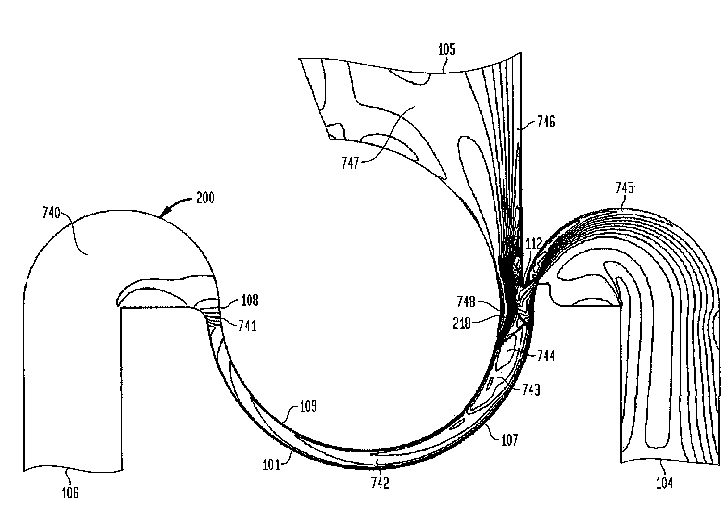
[0180]In a third embodiment, the process gas also includes a substantially liquid constituent that passes the skimmer 112 into the deflection diffuser 104 and remains liquid as it passes through the deflection diffuser 104 and passes external to the separation nozzle. In this manner a portion of the heavier species of the process gas that are separated by the separation nozzle are recovered in liquid form suitable for use as part of a refrigerant system.

[0181]The CFD results depicted in FIGS. 7d and 8b with respect to an embodiment of a type-2 nozzle 200 detail the effect of a preconditioned, or in this embodiment a cooled process gas entering a cooled type-2 nozzle 200. FIG. 8b is a depiction of CFD results of the static temperature of a process gas going through an embodiment of a Type-2 nozzle 200 having the inlet gas pressure of 29 psig and an inlet gas temperature of 434° R. It can be seen at point 827 where T=434°, that the gas enters the inlet gas reservoir 106 and continues ...

Example

[0246]A first embodiment of a multi-stage, single source, separation loop assembly whereby raw feed gas is introduced at only a single stage 2400, also described as a source separation loop 2500, is depicted in FIG. 22. In the schematic of the source separation loop 2500, the elements of the stage 2400 are simplified into a schematic compressor 2502 and a the stage nozzle module 2190. The schematic compressor 2502 generally in the case of the stage 2400 embodiment described in FIG. 21, comprises the following elements: (a) compressor vessel 2420; (b) compressor 2410; (c) pulse vessel 2404; (d) the valves interconnected each of the aforementioned elements (e.g., the nozzle valve 2402); and, (e) sensors (e.g., the temperature sensor 2432). Effectively, the schematic compressor 2502 represents all elements of the stage 2400 external to the stage nozzle module 2190 or the outlet manifold of the stage nozzle module 2190. Each stage 2400 present in the source separation loop 2500 is label...


PUM

PropertyMeasurementUnit
Fractionaaaaaaaaaa
Fractionaaaaaaaaaa
Angleaaaaaaaaaa

Abstract

Multiple designs and methods for aerodynamic separation nozzles and systems for integrating multiple aerodynamic separation nozzles into a single system are disclosed herein. These aerodynamic separation nozzles utilize a combination of aerodynamic forces and separation nozzle structure to induce large centrifugal forces on the gases that in combination with the structure of the nozzle are used to separate heavier constituents of the process gas from lighter constituents. In some embodiments a number of separation nozzles are combined into a single system suitable for dynamic processing of a process gas. In other embodiments the separation nozzles are temperature controlled to condition the incoming gas to a temperature in order to encourage a phase change in certain constituents of the gas to occur within the nozzle to further enhance separation.

Description

CROSS-REFERENCE TO RELATED APPLICATIONS[0001]This application claims the benefit of U.S. Application No. 61 / 080,672.TECHNICAL FIELD[0002]The subject matter described herein relates to devices, systems, and methods related to the separation and concentration or depletion of various constituents of a flow or gas, including gas species, particles, and so forth.BACKGROUND[0003]Aerodynamic separation of gas constituents is useful for a number of industrial and commercial applications. An aerodynamic separation nozzle, or, as used herein, a separation nozzle, uses aerodynamic effects and forces generated by high speed flow through structures to apply large centrifugal and aerodynamic forces to gases flowing through those structures to urge the various gas species that comprise a separation gas to be separated (i.e. process gas) apart thereby enabling separation of the gas species. The combination of the centrifugal forces and the design of the structure are adapted to the type of gas spec...

Claims


Application Information

Patent Timeline
IPC IPC(8): B01D29/00
CPCB01D45/12B01D53/002B01D51/10B01D45/04B01D50/00B01D53/24
Inventor BLOOM, MICHAEL R.
Owner TENOROC
Why Eureka
Try Eureka