
Push-pull two wavelength fabry perot sensor for fiber optic acoustic sensor arrays

a sensor array and fiber optic technology, applied in the field of push-pull two-wavelength fabryperot sensor system for sensing acoustic pressure, can solve problems such as difficulties in implementing such sensor arrays

Active Publication Date: 2010-01-14
NORTHROP GRUMMAN GUIDANCE & ELECTRONICS
View PDF1 Cites 25 Cited by
  • Summary
  • Abstract
  • Description
  • Claims
  • Application Information

AI Technical Summary

Benefits of technology

"The invention is a fiber optic sensor system that uses two-wavelength interferometry to measure acoustic pressure waves. The system overcomes problems caused by optical power fluctuations in previous interferometric systems. The sensor system includes a laser source, optical fibers, and a detector array. The sensor system produces interferometer output signals in response to an acoustic pressure wave incident upon the sensor. The detector array produces electrical signals in response to the interferometer output signals, which are processed to indicate pressure from the acoustic pressure wave. The sensor system may also include an optical on-off switch and a time division multiplexed architecture or a fan-out architecture to couple the sensor to the optical fibers. The sensor system may also include a Fabry-Perot interferometric sensor formed to include a single mode optical fiber, a diaphragm, and a multimode optical fiber. The sensor system can provide accurate and reliable measurements of acoustic pressure waves."

Problems solved by technology

The use of Fabry-Perot sensors in fiber optic acoustic sensor arrays has been proposed many times. However, difficulties are encountered in implementing such sensor arrays with Fabry-Perot interferometers.
Fiber optic sensor systems have power fluctuations associated with source lasers, time dependent polarization effects in the fiber, and other disturbances between the source laser and sensors and between sensors and photodiode detectors.

Method used


Image

  • Push-pull two wavelength fabry perot sensor for fiber optic acoustic sensor arrays
  • Push-pull two wavelength fabry perot sensor for fiber optic acoustic sensor arrays
  • Push-pull two wavelength fabry perot sensor for fiber optic acoustic sensor arrays

Examples


Embodiment Construction

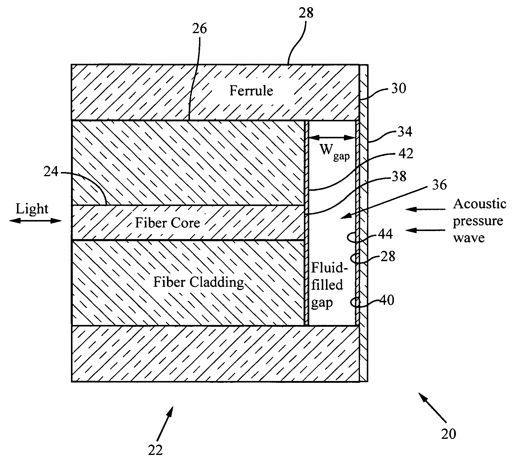
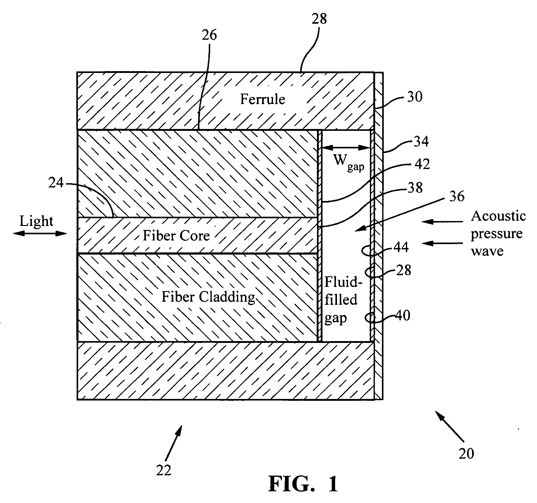
[0026]FIG. 1 illustrates a Fabry Perot interferometer 20 designed for incorporation into a fiber optic sensor array. The Fabry Perot interferometer 20 comprises an optical fiber 22 having a core 24 and a cladding 26 that surrounds the core 24. Optical fiber normally has a protective jacket (not shown). In the portion of the optical fiber 22 shown in FIG. 1 the jacket has been removed and replaced with a ferrule 28 that is preferably formed of a hollow glass rod. An end 30 of the ferrule 28 extends a small distance beyond the core 24 and cladding 26 to form a small cavity 32. A diaphragm 34 is bonded to the outer end 30 of the ferrule 28 such that there is a small gap 36 between the diaphragm 34 and the optical fiber end 38. The diaphragm 34 may be formed of silica. The gap 36 preferably is filled with a fluid such as oil or other substance that has a good impedance match with water.

[0027]A light wave in the optical fiber 22 exits the optical fiber end 38 and enters the fluid filled ...


PUM


Abstract

Two optical wavelengths are used to interrogate a fiber optic Fabry-Perot sensor having a moveable diaphragm that changes the width of a gap between two reflective surfaces. By picking the right operating point for the gap, the power output for one wavelength increases as the gap width changes and the power for the other wavelength decreases. A ratio of the difference of the two powers over the sum of the two powers is formed to generate a detected signal independent of power and phase fluctuations in a fiber between signal sources and sensor and between sensor and detector. This ratio, which is called the visibility, has a response proportional to the pressure of acoustic disturbances that move the diaphragm. The push-pull sensor can be used with both TDM and CW fan-out array architectures.

Description

CROSS REFERENCE TO RELATED APPLICATION [0001]Applicant claims priority for this application based upon U.S. Provisional Application Ser. No. 61 / 134,509, filed Jul. 10, 2008.BACKGROUND OF THE INVENTION [0002]This invention relates generally to a Fabry Perot interferometer for use in a fiber optic sensor array to sense changes in acoustic pressure. This invention relates particularly to a two-wavelength Fabry-Perot sensor system for sensing acoustic pressure.[0003]The use of Fabry-Perot sensors in fiber optic acoustic sensor arrays has been proposed many times. However, difficulties are encountered in implementing such sensor arrays with Fabry-Perot interferometers. Fiber optic sensor systems have power fluctuations associated with source lasers, time dependent polarization effects in the fiber, and other disturbances between the source laser and sensors and between sensors and photodiode detectors.SUMMARY OF THE INVENTION [0004]This invention provides a two-wavelength Fabry-Perot int...

Claims


Application Information

Patent Timeline
Patent Type & Authority Applications(United States)
IPC IPC(8): G01B9/02
CPCG01H9/004
Inventor HALL, DAVID B.
Owner NORTHROP GRUMMAN GUIDANCE & ELECTRONICS
Learn More