Multilayer Structure Measuring Method and Multilayer Structure Measuring Apparatus

a multi-layer structure and measuring method technology, applied in the field of multi-layer structure measuring methods and multi-layer structure measuring apparatuses, can solve the problems of requiring precise position control of reference mirrors and consuming a lot of time for measurements, and achieve the effect of improving measuring precision

Inactive Publication Date: 2010-01-14
CANON KK
View PDF6 Cites 48 Cited by
  • Summary
  • Abstract
  • Description
  • Claims
  • Application Information

AI Technical Summary

Benefits of technology

[0024]According to the present invention, in a multilayer structure measuring apparatus, it is possible to obtain a tomographic image of which measuring precision is improved.

Problems solved by technology

Such a scheme not only takes much time for measurements but also requires precise position control of the reference mirror.

Method used


Image

  • Multilayer Structure Measuring Method and Multilayer Structure Measuring Apparatus
  • Multilayer Structure Measuring Method and Multilayer Structure Measuring Apparatus
  • Multilayer Structure Measuring Method and Multilayer Structure Measuring Apparatus

Examples


first embodiment

[0043]In a first embodiment of the present invention, reference will be made to an optical coherence apparatus to which the present invention is applied, while using the accompanying drawings.

[0044]

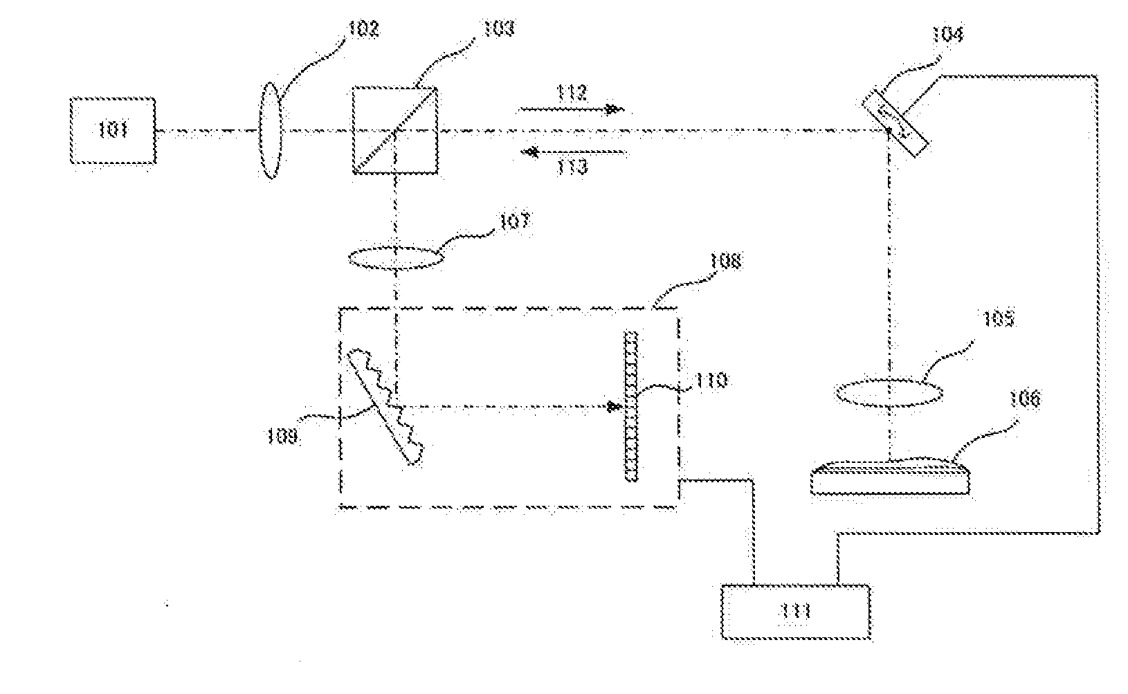
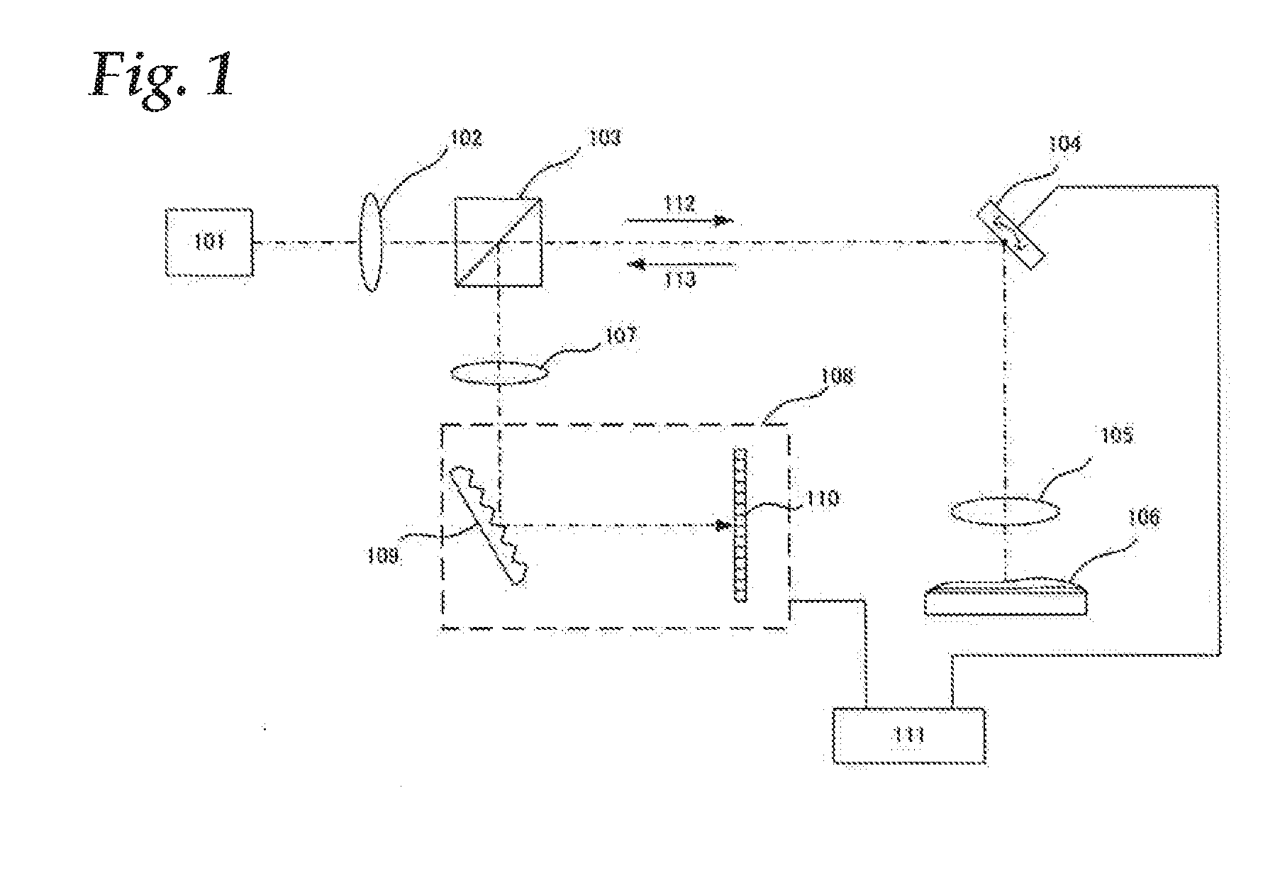
[0045]First of all, the construction of the optical coherence apparatus will be roughly described while referring to FIG. 1. Measurement light emitted from a light source 101 arrives at a sample or specimen 106 such as a semiconductor, which is an object to be observed, through a lens 102, a beam splitter 103, an XY scanner 104, and an object lens 105. A transparent film is disposed on a surface of the sample, and the light reflected by the surface of the sample and an interface between the film and the sample arrives at a spectroscope 108 through the object lens 105, the XY scanner 104, the beam splitter 103, and an imaging lens 107.

[0046]For the light source 101, a halogen lamp or the like is used which has a wavelength of 400˜800 nm, for instance. Here, for the spectroscope 108, a diff...

second embodiment

[0087]In a second embodiment of the present invention, reference will be made to an optical coherence apparatus of a construction which uses a reference mirror, while using the accompanying drawings. Here, the following description will be made mainly about differences from the first embodiment.

[0088]

[0089]First of all, reference will be made to the construction of the optical coherence apparatus according to this second embodiment by using FIG. 4. The light emitted from a light source 101 is divided into reference light 404 and measurement light 112 by a beam splitter 103. The measurement light is reflected by a sample 106 which is an object to be observed, so that it is returned as return light 113. On the other hand, the reference light is reflected by a reference mirror 401. Here, the reference mirror 401 can adjust an optical path length by a position adjusting mechanism 402. The reference light is combined with the return light by means of the beam splitter 103. Thus, an optic...

third embodiment

[0109]In a third embodiment of the present invention, reference will be made to an optical system in an ophthalmic optical coherence apparatus to which the present invention is applied, while using FIG. 7. The system has a basic construction of the type using the reference mirror of the second embodiment.

[0110]Construction of an Optical System>

[0111]FIG. 7 illustrates constructing a Mach-Zehnder interference system as a whole. The light emitted from a light source 701 is divided into reference light 705 and measurement light 706 by means of a beam splitter 703-1. The measurement light 706, after being returned, through reflection or scattering, as return light 708 by an eye 707 which is an object to be observed, is combined with the reference light 705 by means of a beam splitter 703-2 to enter a spectroscope 721.

[0112]First, reference will be made to the surroundings of the light source 701. The light source 701 is an SLD (Super Luminescent Diode) that is a typical low coherent lig...


PUM


Abstract

A tomographic image measuring method according to the present invention includes a first step of calculating information corresponding to an optical distance of each layer thickness from a wave-number spectrum, a second step of separating and extracting information of each layer from the information corresponding to the optical distance of each layer thickness, a third step of reconverting information of each layer into a wave-number spectrum, respectively, a fourth step of obtaining a interference wave number from the result of the-third step, a fifth step of calculating an order of interference from the interference wave number and the optical distance of each layer; and a sixth step of calculating the optical distance of each layer by making use of the fact that the order of interference is an integer. Thus, when discrete Fourier transform is used, the measuring precision of layers is improved.

Description

BACKGROUND OF THE INVENTION[0001]1. Field of the Invention[0002]The present invention relates to a technique that measures a multilayer structure by using optical-coherence optical system.[0003]2. Description of the Related Art[0004]Today, as a multilayer structure measuring apparatus (optical coherence apparatus) that measures a multilayer structure by using an optical-coherence optical system, there are used a variety of kinds of such ones. For example, there are a reflection spectrum film-thickness measuring apparatus that measures the thickness of a thin film arranged on a surface of a semiconductor or glass, and an optical-coherence tomographic imaging apparatus (Optical Coherence Tomography: OCT, hereinafter referred to as an OCT apparatus) that images the tomographic structure of a light scattering medium such as a living body or the like. These are the same in using light interference, but the names and / or constructions of the apparatuses are different according to fields of...

Claims


Application Information

Patent Timeline
Patent Type & Authority Applications(United States)
IPC IPC(8): G01B11/02
CPCA61B3/1005A61B3/102G01B11/0625G01B9/02091G01B11/0675G01B9/02044G01B9/02057G01B11/0633
Inventor SUEHIRA, NOBUHITO
Owner CANON KK
Why Eureka
Try Eureka