Drive and positioning method and system for automated switch matrix

a switch matrix and drive technology, applied in the field of telecommunication network infrastructure, can solve the problems of limiting the capacity of the switch matrix, one of the most significant costs faced by telecommunication providers, and generally very difficul

Inactive Publication Date: 2010-01-14
NORDIA INNOVATION
View PDF5 Cites 3 Cited by
  • Summary
  • Abstract
  • Description
  • Claims
  • Application Information

AI Technical Summary

Benefits of technology

[0007]Briefly described and in accordance with embodiments and related features of the invention, there is provided a method and system for automating a switch matrix board for cross-connecting a line in a set of input lines to a line in a set of output lines, such as in automating cross-connects for line pairs in a central office main distribution frame (MDF) of a telecommunication network, for example. The switch matrix board comprises a plurality of interconnected main contact pads disposed thereon for cross-connecting the lines. Furthermore, a plurality of contact sledges driven by drive means that include a plurality of sledge positioning screws for slidably engaging the contact sledge with the main contact pads. In a first embodiment of the invention, the drive means include driving each of the sledge positioning screws with an electric stepper motor, for example. In a second embodiment, two stepper motors cooperate to turn respective lateral positioning screws to move a lateral drive gear into position to engage and rotate a selected sledge positioning screw. In a third embodiment, a single electric motor operating with a magnetic clutch assembly is used to position the lateral drive gear to engage the selected, sledge positioning screw. A controller on the switch matrix board is connected to a position detection system and to the motors to enable accurate positioning of the contact sledge on the switch matrix board.
[0008]In a method aspect of the invention, there is provided method of automating the switch matrix board described above. With the lateral drive gear engaged between a first and a second lateral positioning screws, when rotating the first lateral positioning screw in either a clockwise or counter-clockwise direction, while keeping the second lateral positioning screw stationary, induces lateral movement of the lateral drive gear in either the left or right direction. This moves lateral chive gear into position to engage the selected sledge positioning screw. When the lateral positioning screws are synchronously rotated in opposite directions, the lateral drive gear remains stationary and rotates the sledge positioning screw, which moves the contact sledge. The controller uses the position detection system for accurately positioning the contact sledge on the matrix.

Problems solved by technology

Management of the copper infrastructure is a highly labor intensive process that results in one of the most significant costs faced by telecommunication providers.
A major drawback with the use of electromechanical relays is that their physical size limits the capacity of the switch matrix.
In other words, to handle more lines more relays must be added, which is generally very difficult given the space limitations of the matrix.
Moreover, robotic solutions tend to exhibit reliability and maintenance issues over the long term that tend to increase costs.
While the prior art solutions have existed for some time, none of them have been able to fulfill requirements for cost-effectiveness and scalability required by telecom service providers.
A disadvantage of the switch matrix described is the limited number of line pairs it can cross-connect and lack of scalability to handle growth in the number of lines in the central office.
Since the capacity of the switch matrix is designed in from the start it is difficult to add switching capacity as conditions dictate in high-growth markets.
Another drawback is that the switch matrix described does not provide a way to determine the position of the shorting elements.
Although it is theoretically possible to calculate position of the shorting elements by counting the stepper motor pulses, the position information would be lost if there is a power outage or if loss of synchronization occurs if the gears slip, for example.
Recovering the position information would require moving the contact elements to a reset position thereby causing highly undesirable service interruptions for the existing connections.
Without precise position information on the shorting elements it is not possible to perform maintenance functions such as cleaning the contact points by periodically moving the shorting elements slightly back and forth without breaking existing connections.

Method used


Image

  • Drive and positioning method and system for automated switch matrix
  • Drive and positioning method and system for automated switch matrix
  • Drive and positioning method and system for automated switch matrix

Examples


first embodiment

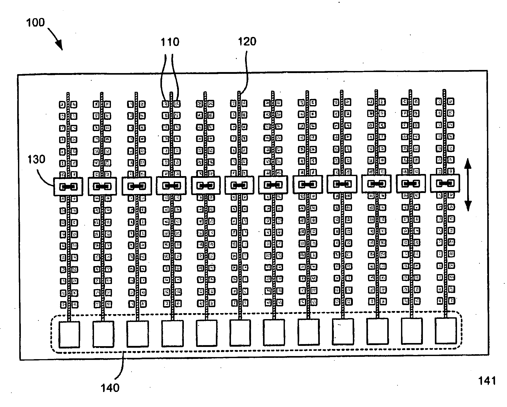
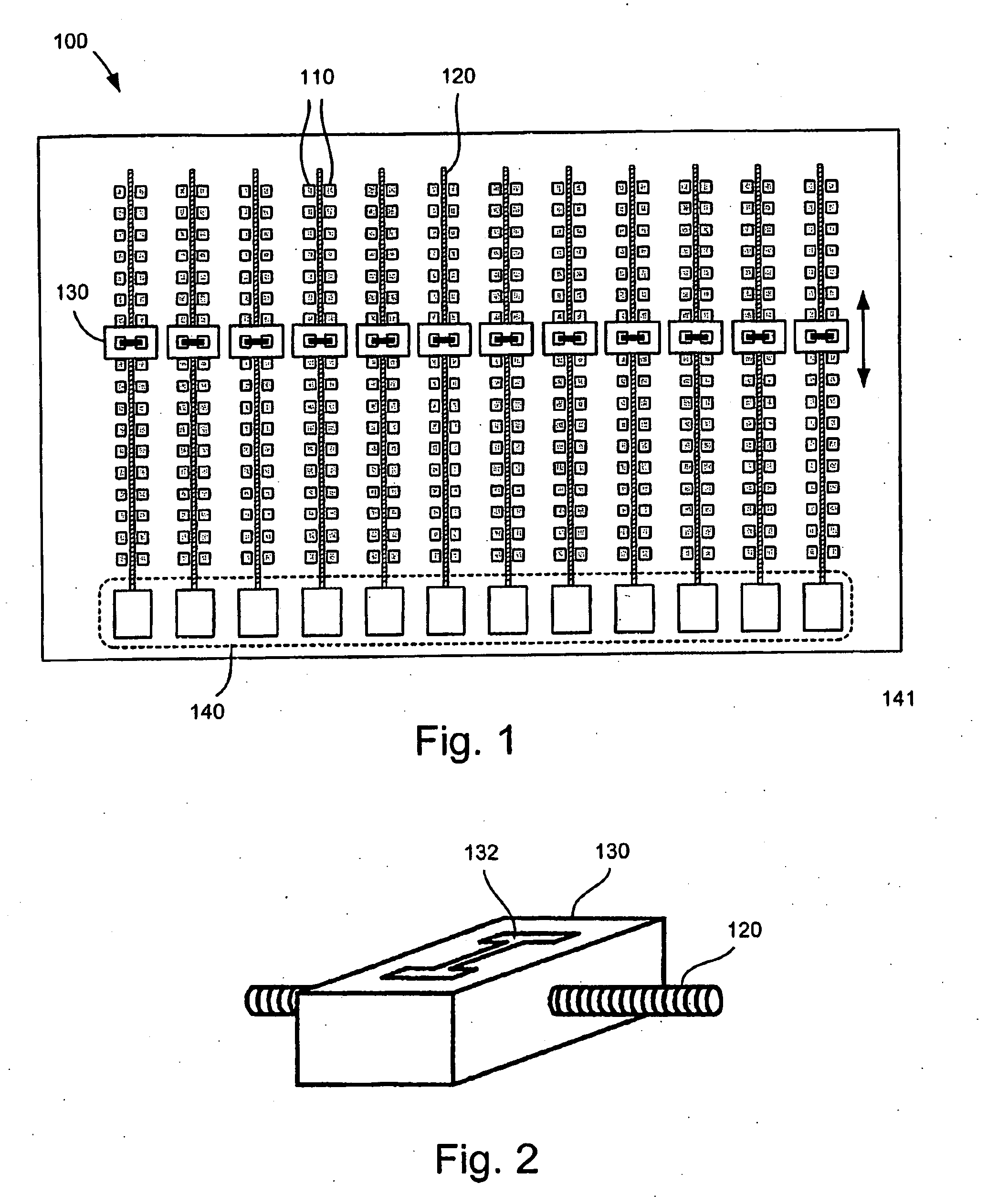
[0022]FIG. 1 shows a diagrammatic top view of an exemplary automated switch matrix operating in accordance with the invention. The switch matrix 100 is configured for cross-connecting a number of input line pails to a number of output line pairs. The switch matrix board comprises a plurality of electrically conducting contact pads 110 that are formed into a printed circuit board (PCB). The contact pads are arranged into a plurality of longitudinal contact trains by which an electrical connection between them is made when a contact sledge 130 is mechanically slid over the contact pads. The contact pads are connected through the PCB to internal conductor layers that interconnect with other contact pads. It should be noted that although the switch matrix of the embodiment is configured for cross-connecting line pairs, it is possible for the matrix to connect any line in a set of input lines to any line in a set of output lines in a so-called any-to-any configuration. Each of the contac...

second embodiment

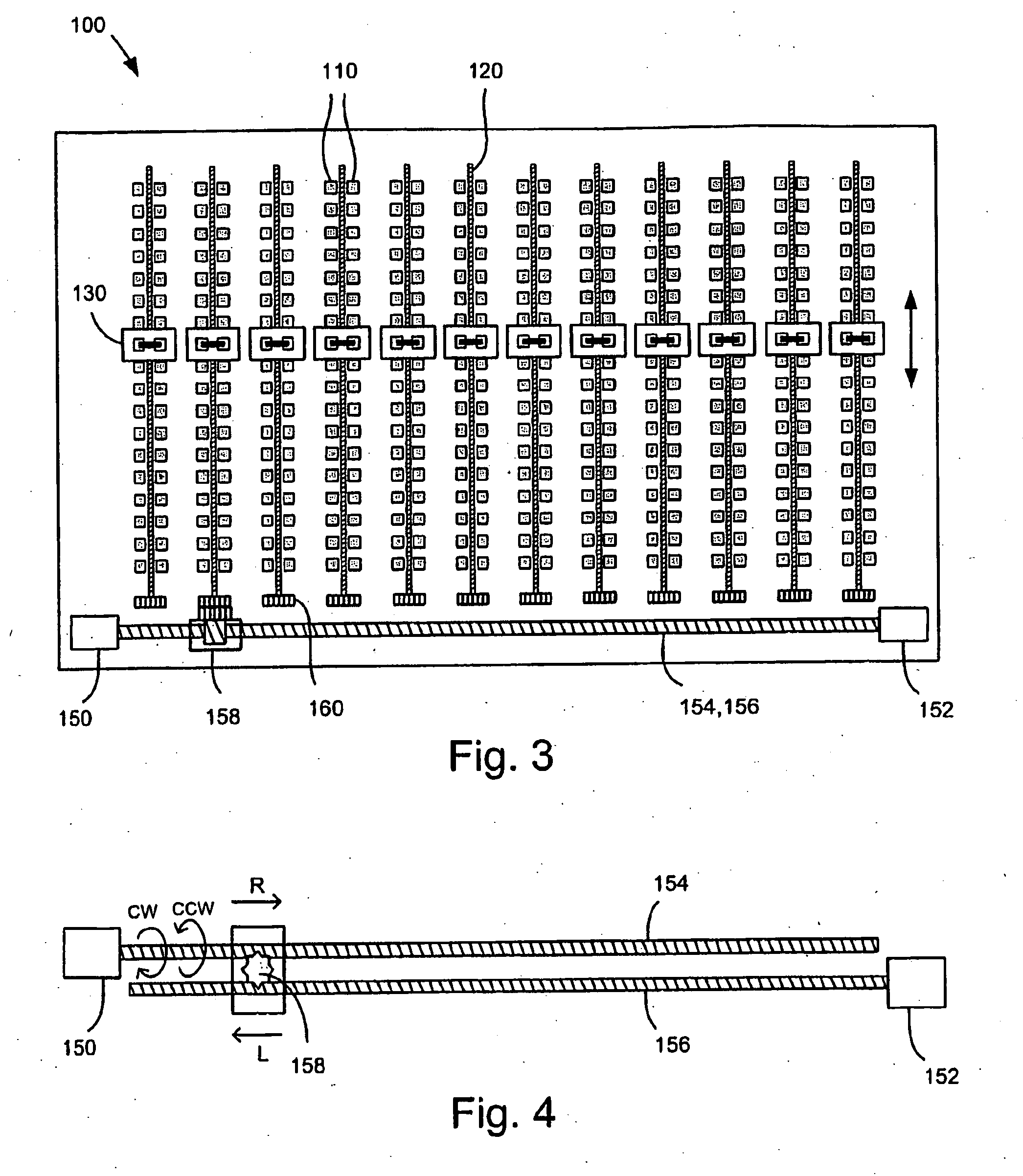
[0024]FIG. 3 is a diagrammatic top view of the exemplary switch matrix operating in accordance with the invention. In the embodiment, the drive means comprises two stepper motors (150,152) i.e. a first motor driving a top lateral positioning screw 154 and the second motor drives a bottom lateral positioning screw 156 (not shown). The lateral positioning screws 154 and 156 operate together to laterally position and induce stationary rotation in lateral drive gear 158. The stepper motors (150,152) operate in combination to move the lateral drive gear 158 to a position where it can engage a specific sledge positioning screw gear 160. Once the lateral drive gear 158 is selectively positioned it engages and rotates the sledge positioning screw gear 160 causing the contact sledge 130 to move longitudinally to cross-connect the desired lines.

[0025]The motion of the lateral drive gear 158 is motivated and controlled in the following manner. For example, when only one of the stepper motors i...

third embodiment

[0029]FIG. 6 shows a side view of the drive mechanism using a single drive motor together with a clutch assembly operating in accordance with a Drive motor 150 rotates the upper and lower lateral positioning screws 154 and 156 via a magnetic clutch assembly 180 in order to move the lateral drive gear 158. By way of example, the lateral drive gear 158 moves right when the upper lateral positioning screw 154 rotates CW and the lower lateral positioning screw 156 is not rotating. This occurs when the drive motor 150 is rotating and the magnetic clutch 180 is disengaged. Similarly, leftward motion of the lateral drive gear 158 is induced when the upper lateral positioning screw 154 rotates CCW with a stationary lower lateral positioning screw 156 caused by a disengaged clutch. Once the lateral drive gear 158 is in position stationary rotation is induced when the upper and lower lateral positioning screws rotate in opposite directions, which occurs when the magnetic clutch 180 is engage...


PUM


Abstract

A method and system for automating a switch matrix board for cross-connecting any line in a set of input lines to any line in a set of output line, to be used e.g. in automating cross-connects for line pairs in a central office main distribution frame (MDF) of a telecommunication network. The switch matrix (100) comprises a plurality of contact sledges (130) driven by a plurality of sledge positioning screws (120) that slidably engage a plurality of main contact pads (110) to cross-connect the lines. In an embodiment of the invention, two electric motors cooperate to position a lateral drive gear (158) to engage and rotate a selected sledge positioning screw (120), which moves the contact sledge. In another embodiment, a single electric motor operates together with a magnetic clutch assembly (180) to position the lateral drive gear to rotate the sledge positioning screw (120). A controller unit is connected to a position detection system and to the motor's to accurately position the contact sledge (130) on the switch matrix board.

Description

FIELD OF THE INVENTION[0001]The present invention relates generally to telecommunication network infrastructure, and more particularly, to a method and system for automating switch matrices for performing cross-connects using drive means and position detection for improved operation.BACKGROUND OF THE INVENTION[0002]In a typical telecommunication network, the central office houses a telephone exchange to which subscriber home and business lines are connected to the network on what is called a local loop. Many of these connections to residential subscribers are typically made using a pair of copper wires, also referred to as a twisted pair, that collectively form a large copper network operated by the telecom provider. Within the central office the line connections between the exchange side and the subscriber side are terminated at a main distribution frame (MDF), which is usually the point where cross-connections between the subscriber lines and the exchange lines are made. Virtually...

Claims


Application Information

Patent Timeline
Patent Type & Authority Applications(United States)
IPC IPC(8): H04M1/00H04QH04Q1/14
CPCH04Q1/145H04Q1/023H04Q1/147
Inventor ROOS, STUREOBERG, JOHAN
Owner NORDIA INNOVATION
Why Eureka
Try Eureka