Device and Method for Coating

Active Publication Date: 2010-01-14
SÄVALLA INVEST AB
View PDF8 Cites 4 Cited by
  • Summary
  • Abstract
  • Description
  • Claims
  • Application Information

AI Technical Summary

Benefits of technology

[0010]Tests performed, using the technique according to the present invention, have shown that surprising improvements are achieved in comparison with conventional technique in respect of the coating's quality and runnability (i.e. a lower web break frequency) with a maintained or improved life span of the revolving rod.
[0011]The soft surface coating of the revolving rod results in better compliance with the more or less rough paper surface and hence it results in decreased “puttying” effect and thereby a better coating of the fibres.
[0012]The cause of the improved runnability is probably that due to the soft surface of the rod being deformed by the particles it will more easily will let particles pass, which particles may be present in the paper or paperboard web, or in the coating mix. Directly after the passage of a particle, the surface coating material will then return to its initial position.
[0023]By application of the present invention, such problems will be diminished or even eliminated, by the rod revolving such that its surface gets lubricated and cooled by the lubrication grooves in the rod cradle. The lubricating agent is usually water but an improved lubricating and cooling effect can be achieved by addition of lubricating and cooling enhancing additives to the water.

Problems solved by technology

Since it is the primary task of the coating rod to level out and wipe off any excess of a coating liquid containing hard particles such as titanium dioxide and / or calcium carbonate, the rod is exposed to continuous wear.
When the rod has experienced a certain degree of wear, it needs to be replaced.
Such exchanging of rods implies large costs, partly due to the cost of the rod itself and partly due to the loss of production caused by the exchanging of rods.
The hard face of the rod means however that the quality of the coating layer will not be optimal in some fields of application for the technique.
Such quality defects are caused by the running web, normally of paper or paperboard, not having a completely smooth surface.

Method used


Image

  • Device and Method for Coating
  • Device and Method for Coating
  • Device and Method for Coating

Examples


Embodiment Construction

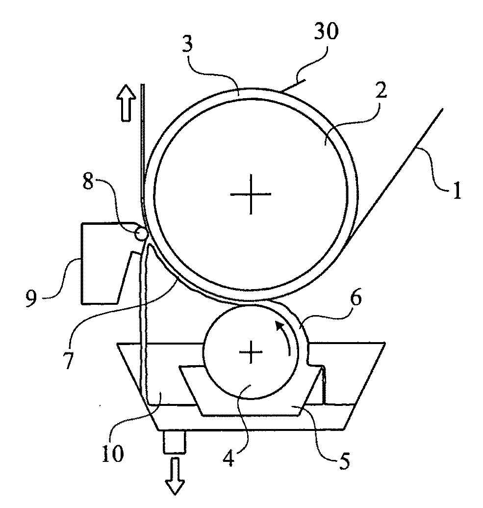
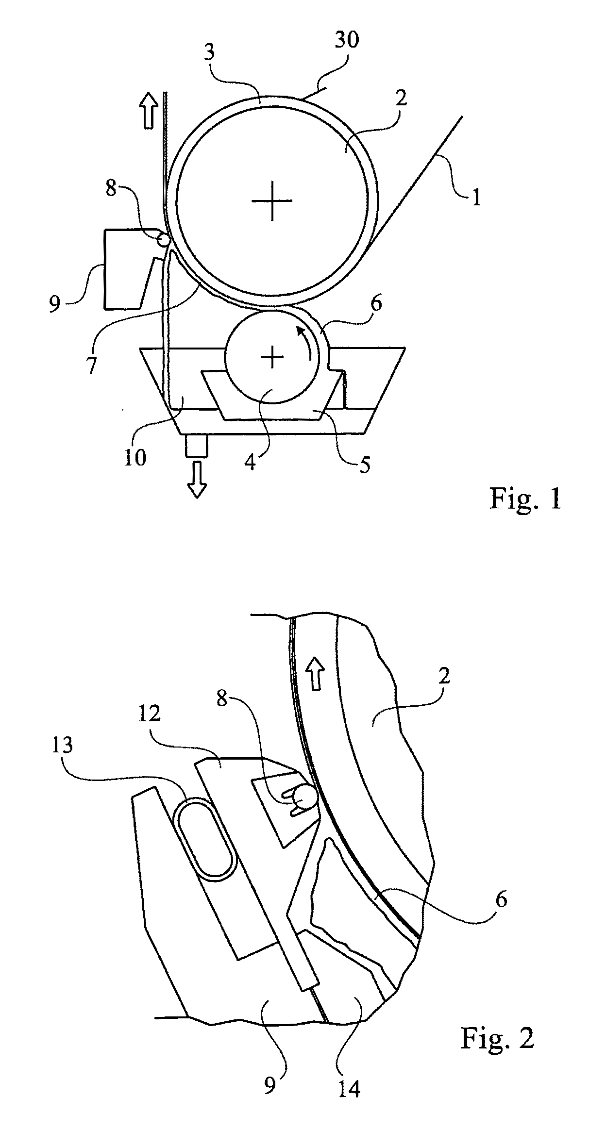
[0037]FIG. 1 shows a revolving rod 8 with a counter pressing roll 2 having a hard surface 3. The coating mix 6 is applied in excess to the web 1 by a traditional method. The figure shows an example of a method of application in which an application roller 4 is submerged in a tray 5 with the coating mix 6. When the roller 4 is rotated, coating mix 6 is fed to the gap formed between the counter pressing roll 2 and the application roller 4. In this nip excess dosing takes place.

[0038]The pre-dosed coating layer 7 is then given its final dosing by the soft rod 8. The rod unit is mounted on a carrier beam 9. The excess of coating mix 6 is led via a collecting tray 10 to a traditional circulation system. The surface of the counter pressing roll 2 can easily be kept clean by use of a traditional cleaning doctor blade 30, which for example can be counter positioned as is schematically shown in FIG. 1.

[0039]In traditional use of a revolving rod, the hard rod is abutting the paper surface. A ...


PUM

PropertyMeasurementUnit
Thicknessaaaaaaaaaa
Thicknessaaaaaaaaaa
Thicknessaaaaaaaaaa

Abstract

A dosing device for the application of a coating mix (6) onto a running web, in particular a paper or paperboard web (1), which device comprises a rod (8) that is supported revolvingly over its entire length in a rod cradle (12), and a pressing device (13) acting on the rod cradle and producing a pressure of the rod onto the web (1) and onto the holding-on device (2, 17, 15) of the web, the rod (8) being provided with a wear resistant surface coating (15) with a hardness of about 10 to about 100 according to Shore A. The invention also relates to methods of using said rod, and to said revolving rod.

Description

TECHNICAL FIELD[0001]The present invention relates to a dosing device for the application of a coating mix onto a running web, in particular a paper or paperboard web, which device comprises a rod that is supported revolvingly over its entire length in a rod cradle, and a pressing device that produces a pressure of the rod onto the web and onto the counter pressing device of the web. The invention also relates to a revolving rod for the application of a coating mix onto a running web. The invention also relates to methods for coating by use of the revolving rod according to the invention.PRIOR ART[0002]The traditional technique of coating with a revolving rod (see e.g. EP 0 541 502) is based on a revolving rod that is supported over its entire longitudinal direction in a rod cradle and that doses the coating mix onto the running web. The revolving rod is made of steel and is usually provided with a wear resistant surface coating of a hard material such as chromium or a ceramic mater...

Claims


Application Information

Patent Timeline
IPC IPC(8): B05D1/28B05C1/08
CPCB05C1/0817B05C1/0826B05C1/0834B05C1/0865D21H25/12B05C11/025B05C11/028D21H23/56B05C9/04B05C11/02D21H23/22D21H23/32D21H23/52
Inventor ERIKSSON, TOREKARLSSON, HAKAN
Owner SÄVALLA INVEST AB
Why Eureka
Try Eureka