
Machine for shaping an eyeglass lens, the machine being provided with a turnable tool-carrier having a plurality of working tools mounted thereon

Active Publication Date: 2010-01-14
ESSILOR INT CIE GEN DOPTIQUE
View PDF11 Cites 16 Cited by
  • Summary
  • Abstract
  • Description
  • Claims
  • Application Information

AI Technical Summary

Benefits of technology

[0011]An object of the present invention is to increase the variety of lens-processing operations made available by a shaper machine that includes a rotary tool-carrier, while continuing to have a machine that is compact.

Problems solved by technology

Such a machine occupies a large amount of space and is expensive because it requires at least one motor to be provided per working module.
The variety of lens-processing operations that can be performed with that tool-carrier is therefore limited.

Method used


Image

  • Machine for shaping an eyeglass lens, the machine being provided with a turnable tool-carrier having a plurality of working tools mounted thereon
  • Machine for shaping an eyeglass lens, the machine being provided with a turnable tool-carrier having a plurality of working tools mounted thereon
  • Machine for shaping an eyeglass lens, the machine being provided with a turnable tool-carrier having a plurality of working tools mounted thereon

Examples


Embodiment Construction

[0051]The following description with reference to the accompanying drawings given by way of non-limiting example makes it well understood what the invention consists in and how it can be reduced to practice.

[0052]In the accompanying drawings:

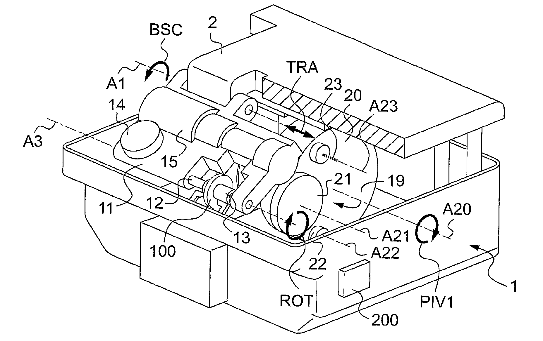
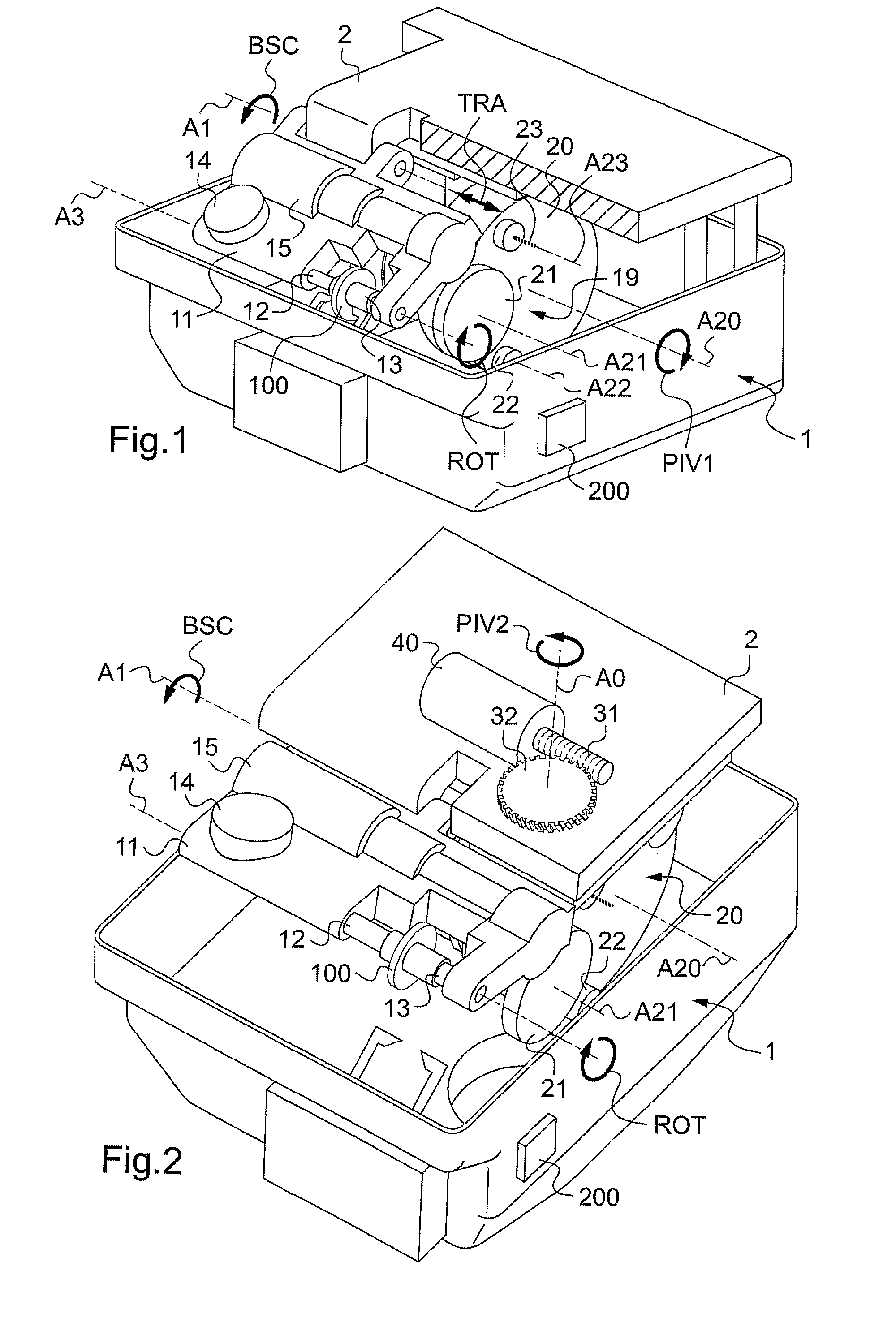
[0053]FIG. 1 is a perspective view of a shaper machine of the invention;

[0054]FIG. 2 is a perspective view from another angle of the shaper machine of the invention, and showing means for swiveling the tool-carrier;

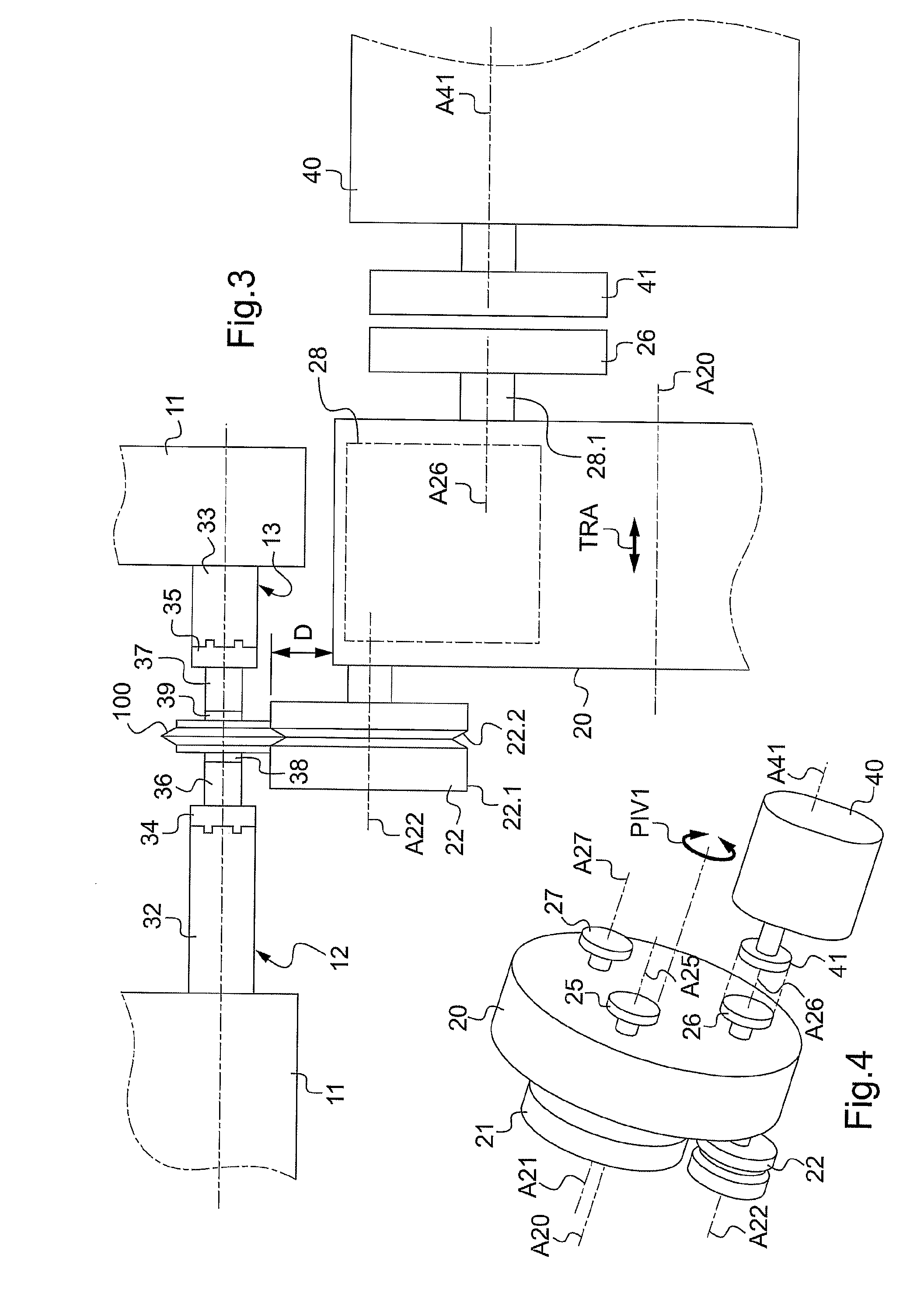
[0055]FIG. 3 is a fragmentary elevation view of the tool-carrier, showing the end of shaping a lens of very small diameter by means of a beveling grindwheel projecting from the tool-carrier; and

[0056]FIG. 4 is a fragmentary diagrammatic perspective view showing the declutchable means for coupling the working tools with the common motor that drives them in rotation.

[0057]FIGS. 1 and 2 show a shaper machine for shaping a corrective and / or tinted ophthalmic lens 100 for fitting to a pair of eyeglasses. The machine comprises a base-formin...


PUM

PropertyMeasurementUnit
Radiusaaaaaaaaaa
Diameteraaaaaaaaaa

Abstract

The machine includes: elements for supporting the lens and for driving it in rotation about a first axis of rotation, the rotation of the lens being driven by first driver element, a tool-carrier mounted to turn about a second axis of rotation, turning of the tool-carrier being driven by second driver element, a plurality of working tools mounted on the tool-carrier to rotate about tool axes, with at least two of the tools including tools for shaping the periphery of the lens for shaping having distinct tool axes, third driver element for driving relative spacing movements between the first axis of rotation and the second axis of rotation, swivel elements for enabling the tool-carrier to be pivoted relative to the first axis of rotation about a third axis of rotation that extends substantially transversely to the first axis of rotation.

Description

TECHNICAL FIELD TO WHICH THE INVENTION RELATES[0001]The present invention relates in general to mounting ophthalmic lenses of a pair of correcting eyeglasses on a frame, and it relates more particularly to a machine and a method for shaping a lens.TECHNOLOGICAL BACKGROUND[0002]The technical portion of the work of an optician consists in mounting a pair of ophthalmic lenses on the frame selected by the future wearer. To do this, the optician needs to shape each lens, which operation consists in modifying the outline of the lens to adapt the lens to the frame and / or to the desired lens shape.[0003]Conventionally, shaping comprises two main operations comprising an edging operation (often referred to as “roughing”) and a finishing operation that depends on the type of frame.[0004]Edging consists in eliminating the unwanted peripheral portion of the ophthalmic lens in question, so as to bring its outline, which is generally initially circular, down to the arbitrary outline of the rim or...

Claims


Application Information

Patent Timeline
IPC IPC(8): B24B1/00B24B7/00
CPCB24B9/14Y10T82/2508Y10T29/5155Y10T29/511Y10T29/5107B24B13/00G02C13/00
Inventor NAUCHE, MICHEL
Owner ESSILOR INT CIE GEN DOPTIQUE
Features
  • Generate Ideas
  • Intellectual Property
  • Life Sciences
  • Materials
  • Tech Scout
  • Unparalleled Data Quality
  • Higher Quality Content
  • 60% Fewer Hallucinations
Learn More