
Stirring apparatus and method

a technology of viscous media and apparatus, which is applied in the direction of process and machine control, electrical programme control, instruments, etc., can solve the problems of not being able to rotate the fluid in the mixing receptacle, not being able to meet the needs of mixing viscous fluid, so as to avoid sedimentation, avoid clumping, and avoid adverse effects of consistency

Inactive Publication Date: 2010-01-14
HUHNSEAL AB
View PDF9 Cites 17 Cited by
  • Summary
  • Abstract
  • Description
  • Claims
  • Application Information

AI Technical Summary

Benefits of technology

[0022]The stirring apparatus may advantageously be configured to keep heavy particles in suspension in a viscous flowable medium, and / or keep said heavy particles in said viscous flowable medium in motion, and / or substantially prevent sedimentation of said heavy particles in said viscous flowable medium, and / or mix at least two components of said viscous flowable medium; and / or blend at least two components of a viscous flowable medium, respectively, in a receptacle provided and configured for stirring the viscous flowable medium.
[0024]Some embodiments of the invention also provide for cost effectively manufacturability of stirring elements.
[0029]Some embodiments provide for blending a powder into a liquid while avoiding formation of clumps.
[0033]Some embodiments provide for efficient stirring with a minimum of energy required.

Problems solved by technology

However, the device of EP 0542 713 is not suited for mixing viscous fluids as the attack area of the blades provides a too large flow resistance for an effective use in viscous fluids.
The device is not suited for mixing viscous fluids because high rotational resistance of the disclosed device makes it unsuited for mixing of viscous liquids.
However, the conically shaped stirring elements of the apparatus disclosed in U.S. Pat. No. 5,037,209 have a relatively large attack area, leading to a rotation of the fluid in the mixing receptacle around the stirring shaft.
A rotation of the fluid implies a less effective mixing effect as the relative speed between the conically shaped stirring elements and the fluid decreases.
In the case of certain media having a high viscosity, or a high load of heavy particles, there is the risk that a plug forms within the conically shaped stirring elements of the apparatus disclosed in U.S. Pat. No. 5,037,209, so that medium can no longer flow through the mixing element.
Moreover, manufacturing of the conically shaped stirring elements of the apparatus disclosed in U.S. Pat. No. 5,037,209 is costly.
Furthermore, it is difficult to provide stirring of the lower bottom layer in the mixing container by means of the conically shaped stirring elements of the apparatus disclosed in U.S. Pat. No. 5,037,209.
In addition, the stirring mechanism is difficult to assemble in the mixing container, where only a small inspection door is provided for access to the interior of the mixing container.
The conically shaped stirring elements of the apparatus disclosed in U.S. Pat. No. 5,037,209 are difficult to clean.
Then a time consuming stirring of the cleaning liquid is performed.
Compared with e.g. high pressure cleaning by means of a spray ball, this leads to increased operation costs and environmental drawbacks, especially when the same receptacle is used for different products and changes are frequent, e.g. several times a day.
However, the large blade surface area together with the slant angel give rise to a large energy consumption for the impeller system disclosed in U.S. Pat. No. 6,250,797, when applying it to a flowable medium with high viscosity, as for instance gruel or pap, due to large shear forces as the impeller system rotates.
Furthermore, the slant angel, with which the blades are arranged makes cleaning potential difficult as part of the blades are not reachable using high pressure cleaning, although the slots may ease the cleaning process they substantially add hidden areas with potential growth of bacterial.
Altogether, the mixing system disclosed in U.S. Pat. No. 6,250,797 is not suitable for mixing food or liquid to be served to human or animal.
Also, stirring efficiency is very low due to this fact, i.e. the amount of energy needed for an effective stirring is high in relation to the stirring effect obtained.
Although an effective mixing is achieved the total number of individual blades needed can have an undesired effect on the viscous flowable medium, especially if it contains for example soft particles, such as fruits or other brittle substances.
The proposed construction of the mixing spirals and arranged mixing blades implies possible hidden areas which could promote a growth of bacteria due to insufficient cleaning possible without complete disassembly of the apparatus for cleaning.

Method used


Image

  • Stirring apparatus and method
  • Stirring apparatus and method
  • Stirring apparatus and method

Examples


example

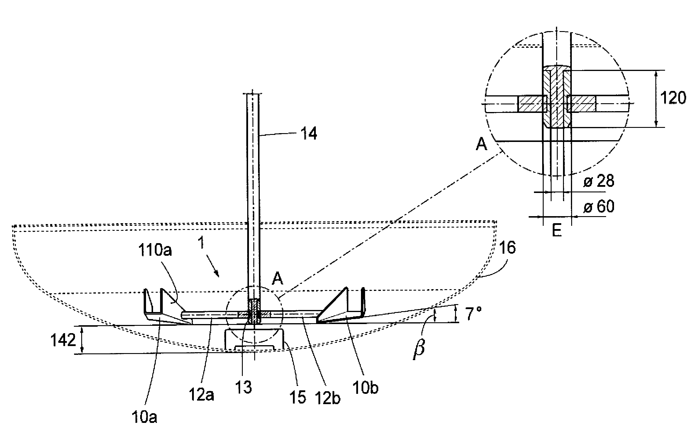
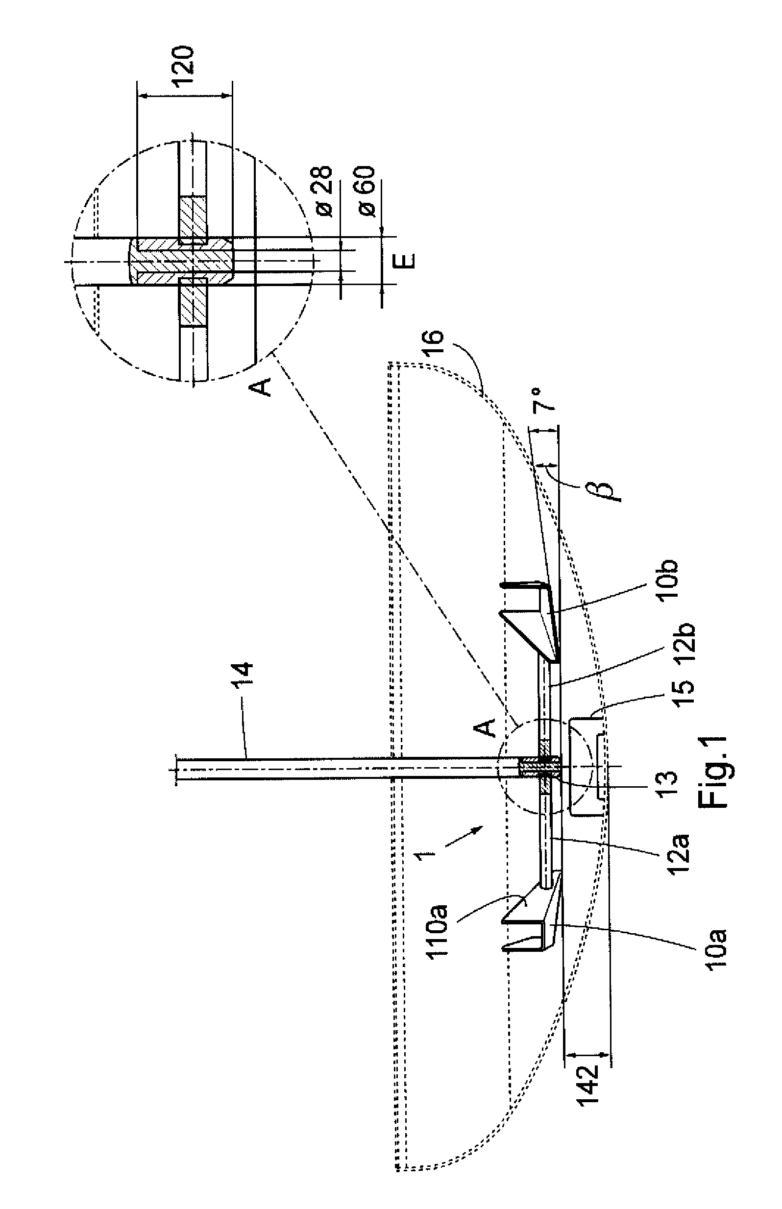
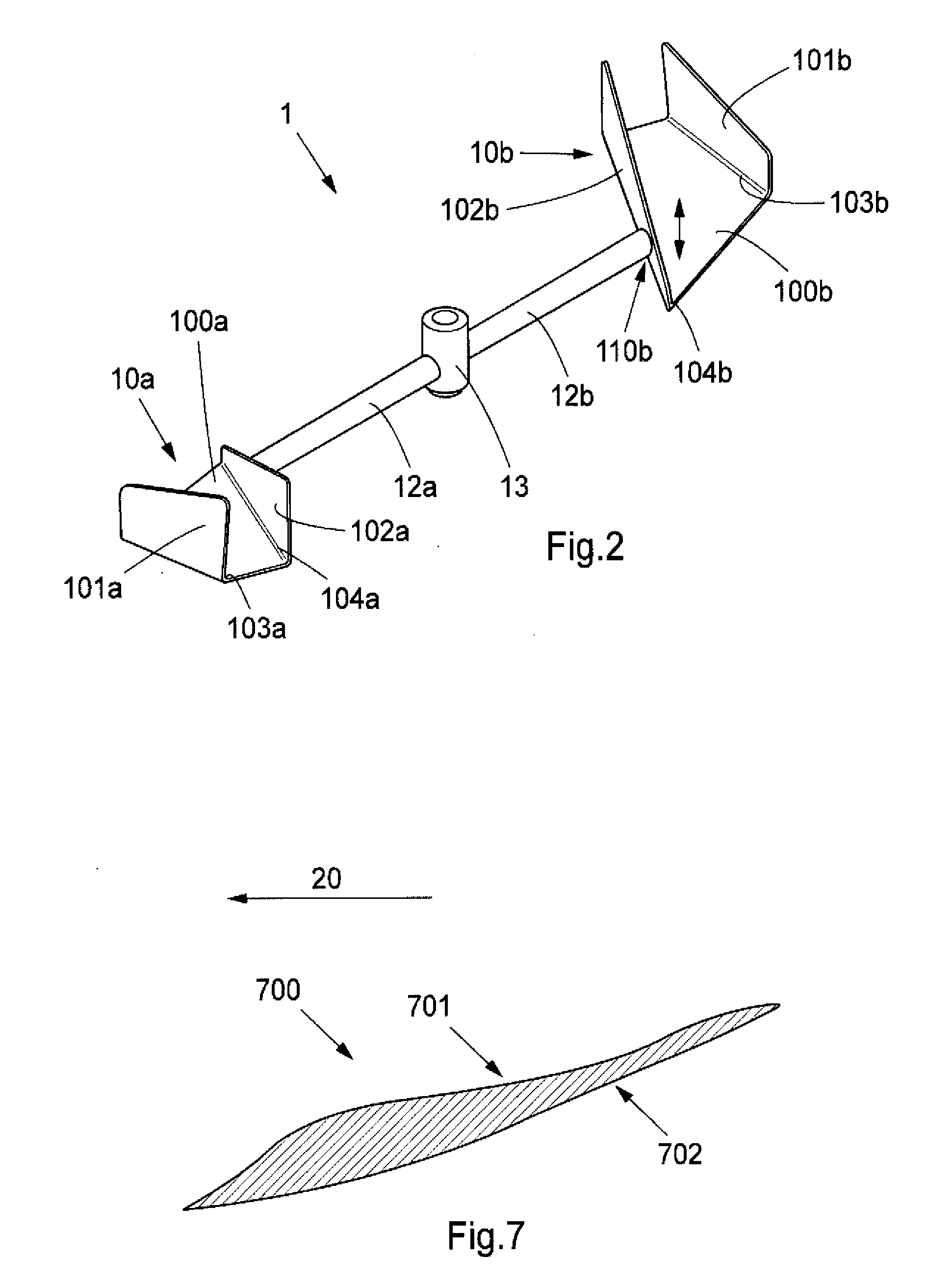
[0081]A stirring apparatus according to the attached Figures was used for stirring a viscous medium.

[0082]The requirements specifically demanded of the apparatus were the following in particular:[0083]The mixing mechanism should be able to mix a creamy substance, such as soured milk or yoghurt, with fruit particles.

[0084]Test Data:[0085]Tank diameter: 3000 mm[0086]Tank height: 4000 mm[0087]Tank content: 20 m3 (20 000 liters)[0088]Medium: fruit cream[0089]Viscosity: 15000 CentiStokes (cSt)[0090]Density: 1[0091]Temperature: 10 DEG C.[0092]Dimensions of stirring elements: according to the attached Figures and related description above.[0093]Drive motor: 2.2 kW[0094]Stirring speed: 200 rpm, respectively.

[0095]Result: An excellent mixing effect was achieved after a mixing time of 20 minutes with low power requirement and operating costs.

[0096]As used herein, the singular forms “a”, “an” and “the” are intended to include the plural forms as well, unless expressly stated otherwise. It will...


PUM

PropertyMeasurementUnit
radial slant angleaaaaaaaaaa
circumferential velocitiesaaaaaaaaaa

Abstract

An apparatus for mixing a viscous flowable medium includes a receptacle for receiving the viscous flowable medium and has a substantially vertically arranged rotatable stirring axle and a stirring assembly that comprises at least one stirring element. In one embodiment, the stirring element is arranged at a lower end of the stirring axle substantially perpendicular thereto for rotation of the stirring element around the stirring axle. The stirring elements are shovel-like and are open towards an end of the stirring axle remote from the lower end and inclined with a slant angle in rotation direction towards a bottom of the receptacle, such that said viscous liquid upon rotation of the stirring axle is at least partly directed upwards in the receptacle by the at least one shovel-like stirring element.

Description

PRIOR APPLICATIONS[0001]This application is a continuation-in-part of International Application No. PCT / EP2008 / 052834, filed on Mar. 10, 2008, which in turn bases priority on Swedish application No. 0700603-4 filed Mar. 10, 2007.FIELD OF THE INVENTION[0002]This invention pertains in general to the field of apparatuses for stirring viscous media, e.g. for mixing purposes or for preventing sedimentation of a media. More particularly, the invention relates to such apparatuses having a stirring axle and perpendicular to the stirring axle arranged stirring elements.BACKGROUND OF THE INVENTION[0003]Various mixing apparatuses are known in the art. For instance, a mixing apparatus has been disclosed in EP 0542 713. The mixing of fluids takes place in a mainly cylindrical mixing vessel by means of a revolving mixing element disposed therein. Homogeneity of a settling fluid in the mixing vessel is maintained by keeping a flow direction in the vessel as vertical as possible. This is ensured by...

Claims


Application Information

Patent Timeline
Patent Type & Authority Applications(United States)
IPC IPC(8): B01F7/00G05B19/02B01F27/94B01F27/906
CPCB01F3/0853B01F3/1221B01F7/00158B01F7/00016B01F15/00201B01F15/00389B01F7/285B01F23/43B01F23/53B01F27/0726B01F27/941B01F35/212B01F35/221422B01F27/06B01F27/1154B01F27/80B01F27/051
Inventor ANDERBERG, GORAN
Owner HUHNSEAL AB
Learn More