High efficiency concentrating photovoltaic module with reflective optics

a photovoltaic module and high-efficiency technology, applied in the direction of pv power plants, thermal-pv hybrid energy generation, semiconductor devices, etc., can solve the problems of reducing the efficiency of solar cells, reducing the reliability or requirement of solar cells, and requiring higher losses, so as to reduce the overall cost of generating electricity per kilowatt hour, improve solar conversion efficiency, and reduce initial costs

Inactive Publication Date: 2010-01-21
AMMAR DANNY F
View PDF6 Cites 59 Cited by
  • Summary
  • Abstract
  • Description
  • Claims
  • Application Information

AI Technical Summary

Benefits of technology

[0007]This invention is directed to a concentrating PV module that improves solar conversion efficiency, lowers initial costs, and therefore reduces the overall cost of generating electricity per kilowatt-hour.
[0008]One aspect of this invention is predicated on the concept of providing a simple, CPV module comprising one or more reflective sun concentrating units arranged in a construction that is highly modular, easily assembled, and lower in initial cost. In one embodiment, each module includes a light-weight aluminum housing tray that mounts a number of solar collectors having a shape approximating that of a parabola and covered by anti-reflection glass that provides a sealed environment. The focal line of such parabola is coincident with a secondary reflector which receives sunlight incident on the primary collectors and reflects such light onto a solar cell mounted in a fixed position slightly below the primary reflector and substantially concentric to the centerline of the primary collector. The primary collector is supported by a frame to add rigidity, and maintain precise location relative to the secondary reflector and the solar cell. A number of individual collectors may be arranged side-by-side to form a solar module of desired size.
[0011]In an alternative embodiment, the solar cells are attached, using solder or epoxy, to a uniquely formulated thin printed circuit board (PCB) with a coefficient of thermal expansion (CTE) that is matched the solar cells. The top layer of the PCB includes copper traces, which provide low loss cell-to-cell electrical interconnection, therefore eliminating the need for interconnect wires.
[0012]Still another embodiment of this invention is designed to increase efficiency by reducing heat in the solar cells. It has been found that when sun radiation is concentrated, so is the amount of heat produced. Cell efficiencies decrease as temperatures increase, and higher temperatures also threaten the long-term stability of solar cells. Therefore, the solar cells must be kept cool in a concentrator system. In this embodiment, a heat spreader made of graphite fibers, weighing 60% less than aluminum and 82% less than cooper, is bonded to the PCB board. The graphite heat spreaders offer thermal conductivity up to 1500 W / mK as compared to about 200 W / mK for aluminum. The heat spreader of the current invention is anisotropic, conducting heat well along its x and y axes but less in the z-axis. As a result, it conducts the heat longitudinally away from the source and thus reduce temperature rise in the solar cell.

Problems solved by technology

However, there are also several deficiencies in current CPV systems, including long focal lengths optic concentrators resulting in substantial module height and weight, intense heat resulting in reduced solar cell efficiency and reliability or requiring active cooling methods, high Electrical resistance in the cell-to-cell connection results in higher losses and lower efficiency, and high precision sun trackers.
Current state-of-the-art in CPV modules, in so far the applicant is aware of at the time of this application, typically are configured in a box like structure, with traditional refractive or reflective optics and low solar-to-electrical conversion efficiency, typically below 24%, due to excessive heat.
The wider acceptance angle reduces the sun tracker accuracy requirements.

Method used


Image

  • High efficiency concentrating photovoltaic module with reflective optics
  • High efficiency concentrating photovoltaic module with reflective optics
  • High efficiency concentrating photovoltaic module with reflective optics

Examples


Embodiment Construction

[0046]The present invention will now be described more fully hereinafter with references to the accompanying drawings, in which preferred embodiments of the invention are shown. This invention may, however, be embodied in many different forms and should not be constructed as limited to the embodiments set forth herein. Rather, these embodiments are provided so that this disclosure will be thorough and complete, and will fully convey the scope of the invention to those skilled in the art. Like numbers refer to like elements throughout.

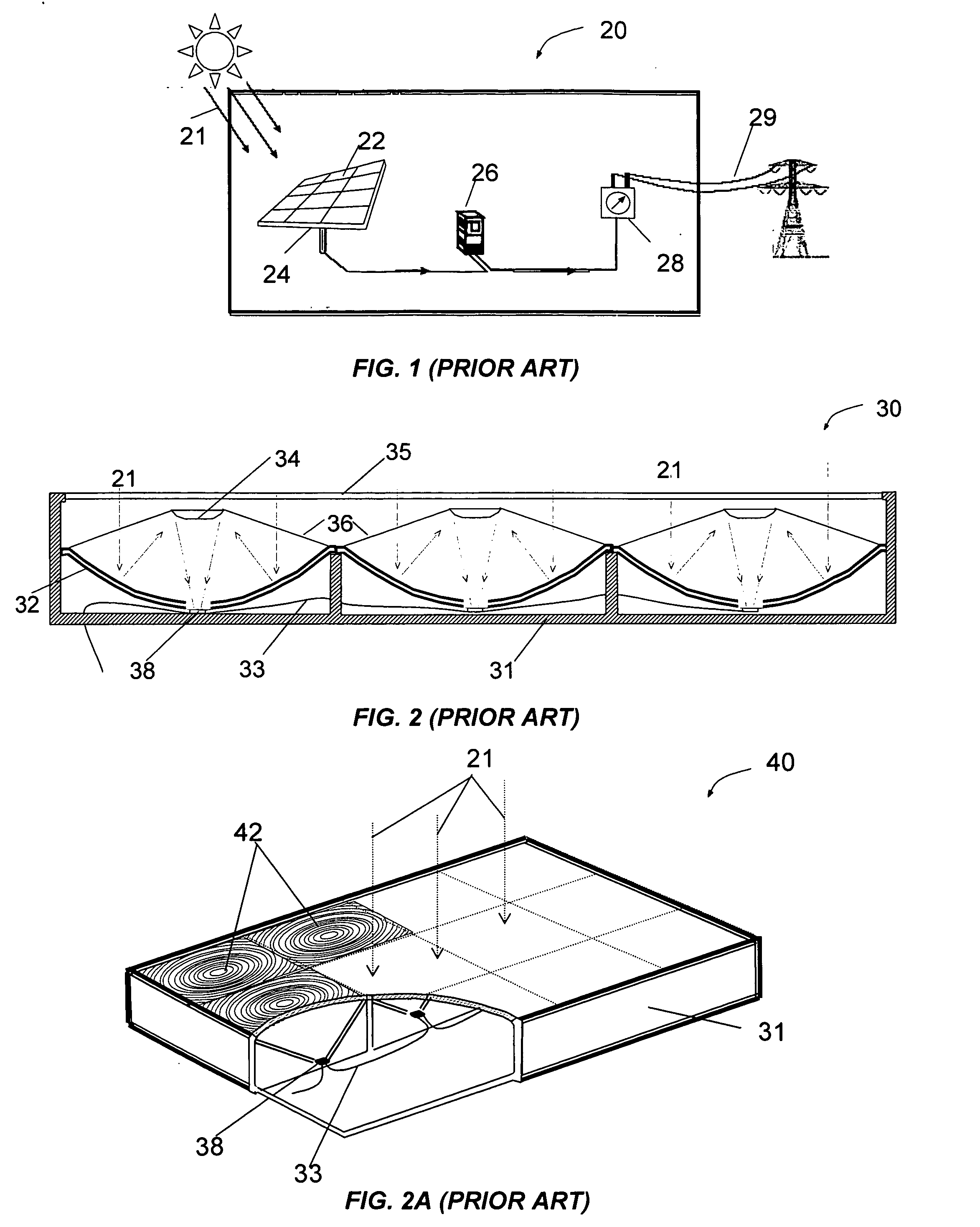
[0047]FIG. 1 shows a typical grid-connected concentrated photovoltaic solar system. The solar array 22 consists of one or more CPV modules which convert sunlight 21 into electricity. The sun tracker 24 is a device that rotates in 2-axes to track the sun across the sky throughout the day to keep the sun rays directly on the solar array. It is advantageous for the solar array to be oriented substantially perpendicular to the position of the sun throughout...


PUM


Abstract

A Concentrating Photovoltaics (CPV) module includes light weight housing, a number of Cassegrain type reflective solar concentrators, a number of multi-junction solar cells and a novel heat spreading system. The primary and secondary reflectors focus the sun over 500 times to maximize the amount of photons collected by the solar cells and converted to electricity. A newly designed soft board material provides coefficient of thermal expansion (CTE) matched carrier for the solar cells and an efficient electrical connectivity method. The carrier board is attached to a specially formulated heat spreader that is specially formulated to conduct heat longitudinally away from the solar cells. The combination of the above creates CPV modules with the highest efficiency and lowest cost per Watt.

Description

CROSS-REFERENCE TO RELATED APPLICATIONS[0001]This application is a continuation-in-part of U.S. application Ser. No. 12 / 043,018, filed Mar. 3, 2008 and entitled “High Efficiency Concentrating Photovoltaic Module Method and Apparatus”.FIELD OF THE INVENTION[0002]The present invention relates to the field of solar power conversion system using Concentrating Photovoltaics (CPV). More specifically, the present invention includes an array of light weight primary and secondary reflective collectors for concentrating sun rays onto an array of solar cells which generate electric power.BACKGROUND OF THE INVENTION[0003]The idea of concentrating sunlight onto a small solar cell had been studied and tried for many years. The primary reason for using concentrators is to be able to use less solar cell material. A concentrator makes use of relatively inexpensive materials such as plastic lenses, or dish reflectors, to capture the solar energy shining on a fairly large area and focus that energy on...

Claims


Application Information

Patent Timeline
Patent Type & Authority Applications(United States)
IPC IPC(8): H01L31/052H01L31/00
CPCH01L31/052Y02E10/52H01L31/0547H01L31/0543H02S40/22H02S40/44Y02E10/60
Inventor AMMAR, DANNY F.
Owner AMMAR DANNY F
Why Eureka
Try Eureka