
Test strip with optical identification patterns and test instrument using the same

a test strip and optical identification technology, applied in the direction of instruments, chemical indicators, material electrochemical variables, etc., can solve the problems of inability to guarantee correct test, user forgetting to insert the attached code card into the test instrument, and the method is too complicated and impractical for a poct user, so as to prevent the user from forgetting

Inactive Publication Date: 2010-01-21
HMD BIOMEDICAL
View PDF16 Cites 34 Cited by
  • Summary
  • Abstract
  • Description
  • Claims
  • Application Information

AI Technical Summary

Benefits of technology

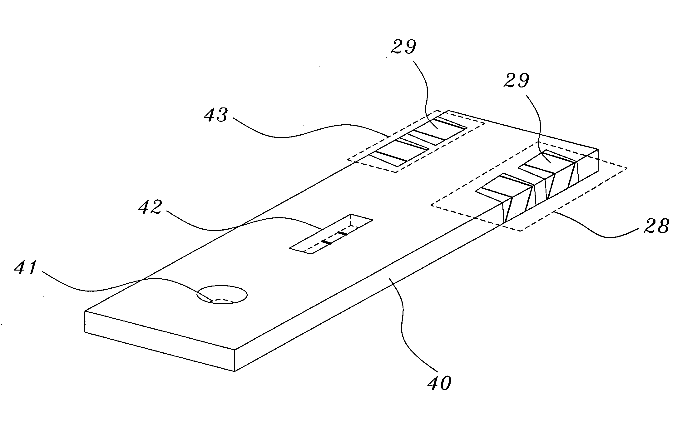
[0019]One objective of the present invention is to provide a test strip with optical identification patterns and a test instrument using the same, wherein a test strip incorporates an identification area having optical identification patterns, and a test instrument has a detector able to read optical identification patterns contained in the test strip and generate related digital identification signals, whereby the analysis parameters, expiry date, batch number, etc. of the test strip are automatically transmitted to the test instrument, and the test instrument is then automatically calibrated. Thus, the present invention can effectively prevent a user from forgetting to calibrate a POCT analyzer.
[0020]To achieve the abovementioned objective, the present invention form optical identification patterns on an identification area of a test strip according to the characteristics of the test strip, and the optical identification patterns will create related digital identification signals. The present invention also proposes a test instrument to cooperate with the test strip. After receiving the digital identification signals, the test instrument can determine the parameter-setting data and product data of the test strip. Thereby, the test instrument can fast and correctly set the analysis parameters of a test strip.

Problems solved by technology

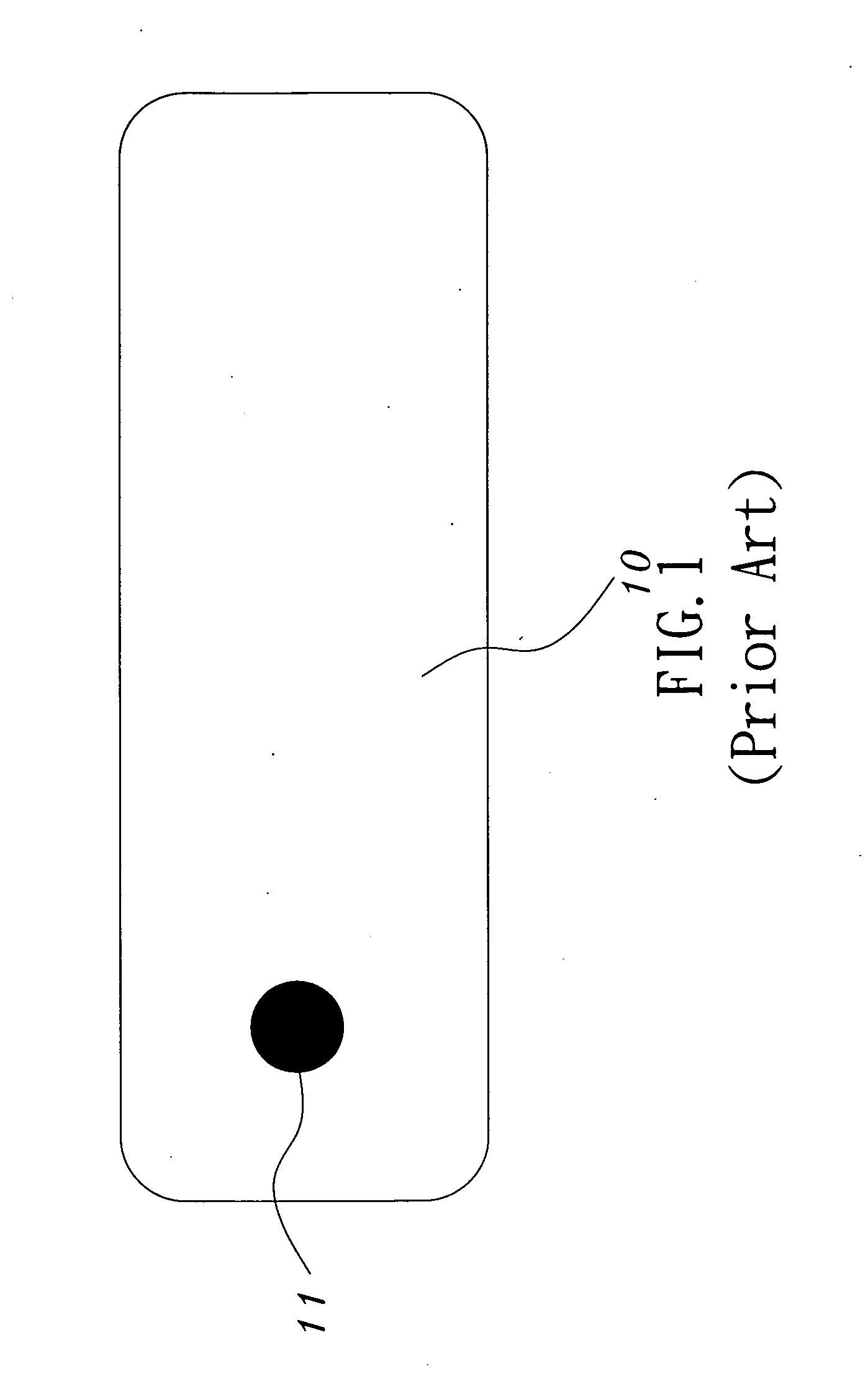
However, such a method is too complicated and impractical for a POCT user, who is not necessarily familiar with such a method.
However, some users may still forget to insert the attached code card into the test instrument when they use a new batch of test strips or reagent.
For POCT users, such a scheme cannot guarantee correct test results yet.
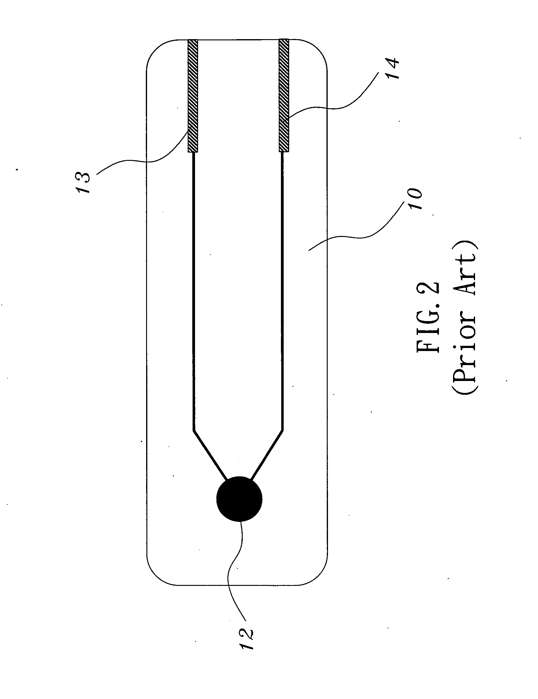
However, a parameter-setting procedure is still needed, and a user may still forget to calibrate the test instrument.
Although the scheme can effectively solve the abovementioned problem, the device has a bulky size and a higher price.
However, it wastes resources, causes an environmental problem and has a high price.
An analyzer with a unique set of parameters: Such a scheme also free users from setting parameters but has a greater error range and a higher production defective fraction.
Although many products to solve the problem have been proposed and sold in the marketplace, all of them still have room to improve.

Method used


Image

  • Test strip with optical identification patterns and test instrument using the same
  • Test strip with optical identification patterns and test instrument using the same
  • Test strip with optical identification patterns and test instrument using the same

Examples


Embodiment Construction

[0029]The present invention proposes a test strip with optical identification patterns and a test instrument using the same, which applies to various POCT analysis devices, such as blood glucose meters, cholesterol meters, and immunological analyzers. The test strip of the present invention is characterized in having a test area and an identification area. The test area is an optical test area, an electrochemical test area, or a color reaction / colorimetric area. The identification area has optical identification patterns, and the test instrument can obtain the digital identification signals from a detector, which is corresponding to the type of optical identification patterns.

[0030]The test strip of the present invention includes three embodiments, and the test strip of each of the three embodiments has an identification area containing optical identification patterns. Among them, a first embodiment involves an optical test area; a second embodiment involves an electrochemical test ...


PUM


Abstract

The present invention discloses a test strip with optical identification patterns and a test instrument using the same characterized in that the test strip incorporates an identification area. Different combinations of optical identification patterns on the identification area create different digital identification signals. After the test strip is inserted into the test instrument, the test instrument will obtain the digital identification signal and learn the test code, analysis parameters, expiry date and batch number of the test strip. Thereby, the test instrument can verify the batch number and expiry date of the test strip, perform calibration according to the analysis parameters, and provide a correct test result. The present invention can provide many sets of digital identification signals to differentiate test strips. Therefore, the present invention can be operated fast, conveniently and correctly and can prevent a user from forgetting to calibrate the test instrument.

Description

BACKGROUND OF THE INVENTION[0001]1. Field of the Invention[0002]The present invention relates to a test strip and a test instrument using the same, particularly to a test strip with optical identification patterns and a test instrument using the same.[0003]2. Description of the Related Art[0004]With the development of bio-test technologies, many tests can be undertaken in a clinic or even by a patient at home. Those tests, such as biochemical tests, immunological tests, gene tests, etc., are originally performed by specialists, like physicians, medical technologists or researchers, in special sites, like hospitals or laboratories, with precision equipments. Such a technology is called POCT (Point of Care Test). Common biochemical POCT tests include tests of glucose, cholesterol, uric acid, etc. Common immunological POCT tests include tests of pregnancy, drugs, tumor markers, glycated hemoglobin, enterovirus gene, etc. POCT technologies and their derivatives can apply not only to med...

Claims


Application Information

Patent Timeline
IPC IPC(8): G01N27/26G01N21/01G01N21/78
CPCG01N21/78G01N33/48771G01N21/8483
Inventor HSU, TIEN-TSAI
Owner HMD BIOMEDICAL
Learn More