Reflow furnace

a reflow furnace and furnace technology, applied in the direction of welding/cutting media/materials, manufacturing tools, welding/cutting apparatuses, etc., can solve the problem of insufficient suction for sending flux fumes to the removal apparatus

Inactive Publication Date: 2010-01-21
SENJU METAL IND CO LTD
View PDF0 Cites 17 Cited by
  • Summary
  • Abstract
  • Description
  • Claims
  • Application Information

AI Technical Summary

Benefits of technology

[0017]A suction pipe for sucking flux fumes needs to extend over the entire heating zone, i.e., over the preheating zone and the main heating zone. In the preheating zone, solvent evaporates from solder paste, and in the main heating zone, flux vaporizes. Therefore, sucking of these vapors and fumes needs to be given first priority. However

Problems solved by technology

In a reflow furnace equipped with a conventional flux fumes removal apparatus,

Method used


Image

  • Reflow furnace
  • Reflow furnace
  • Reflow furnace

Examples


Embodiment Construction

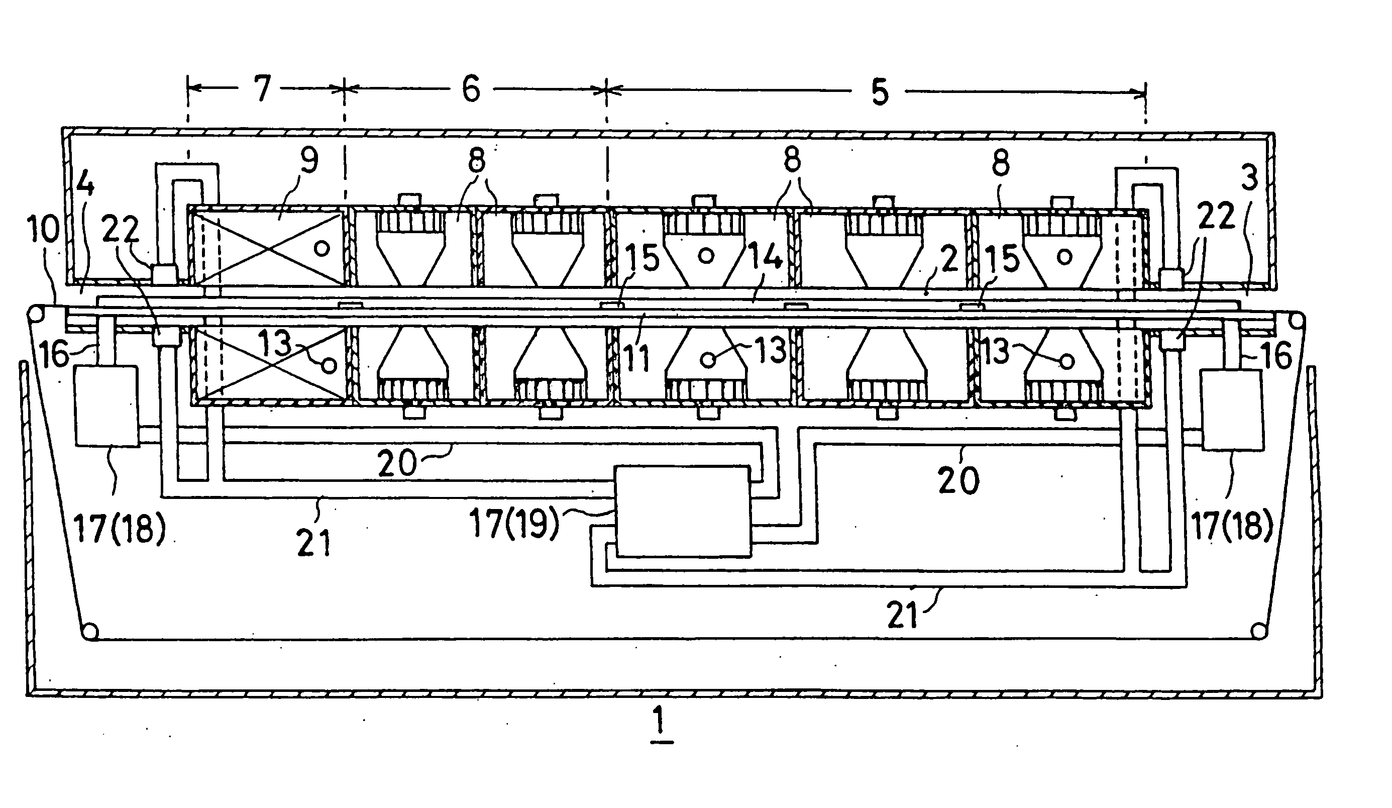
[0022]Below, a reflow furnace according to the present invention will be described based on the drawings. As shown in the drawings, the reflow furnace 1 has a tunnel 2 formed in its lengthwise direction. The inside of the tunnel is formed into a preheating zone 5, a main heating zone 6, and a cooling zone 7 which are arranged in series from an entrance 3 towards an exit 4. Heaters 8 of the type which blow hot air are installed in the upper and lower portions of the preheating zone 5 and the main heating zone 6. Cooling mechanisms 9, 9 are installed in the upper and lower portions of the cooling zone 5.

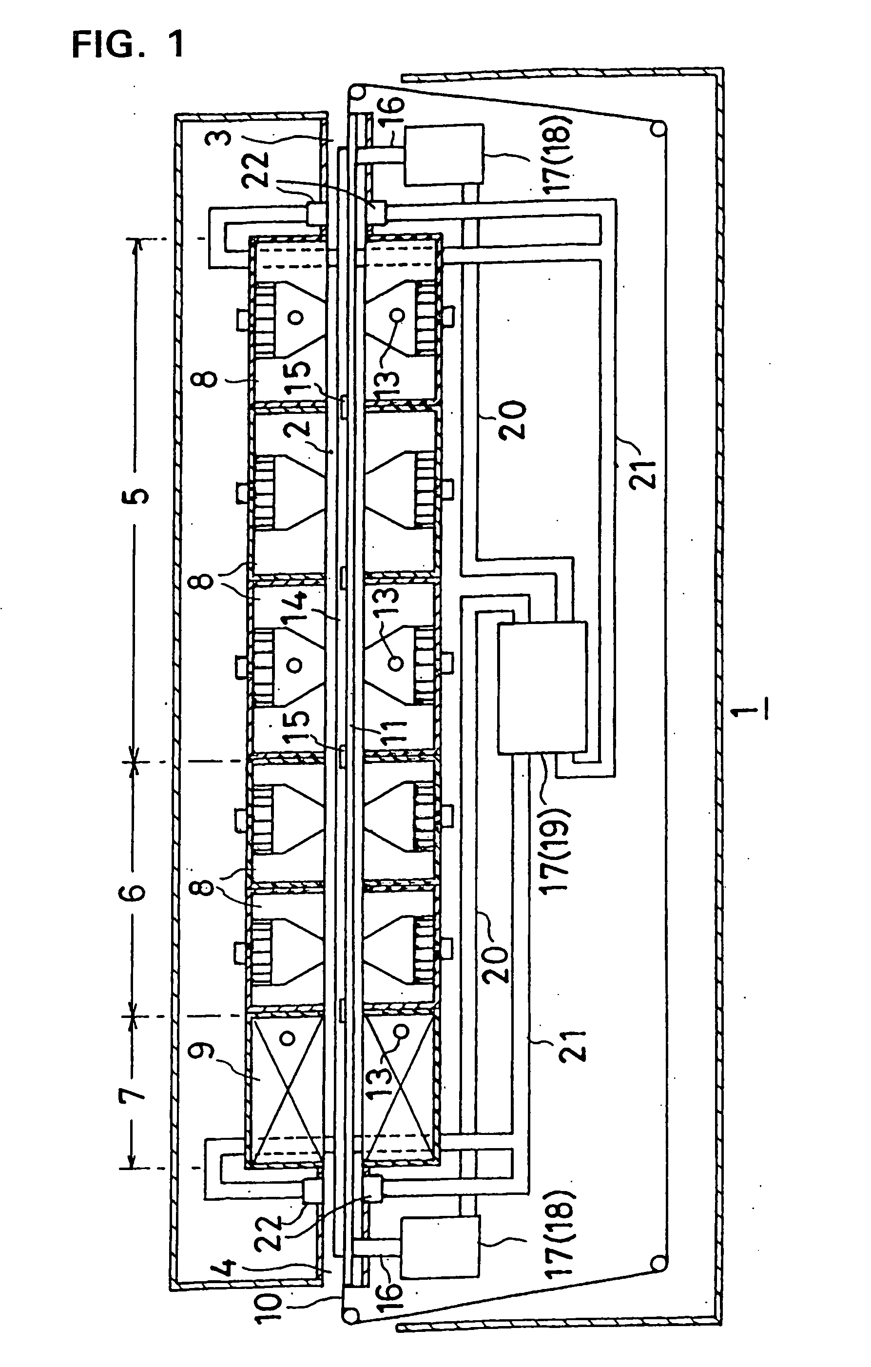
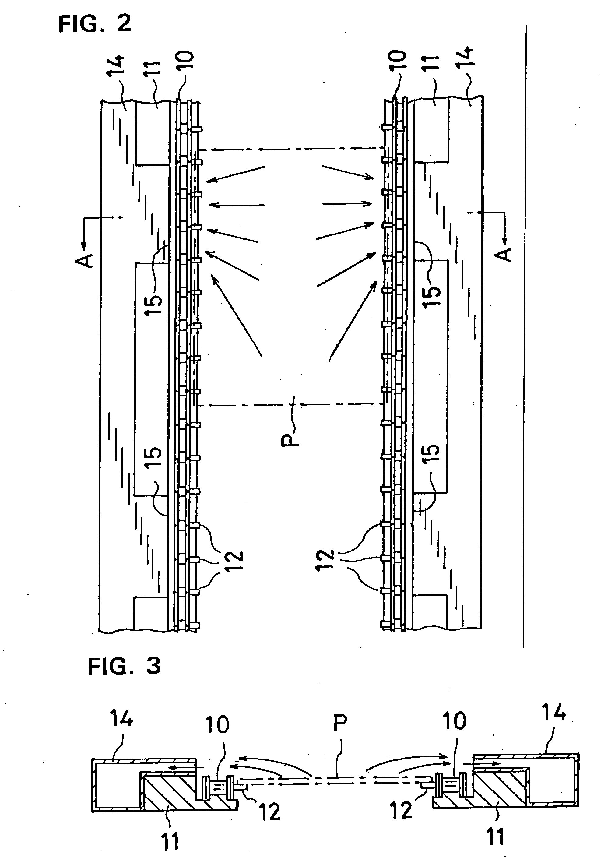
[0023]A pair of conveyors 10, 10 runs inside the tunnel 2 from the entrance 3 towards the exit 4. The conveyors 10 travel atop rails 11. A large number of pins 12 which extend toward each other project from the pairs of conveyors 10, 10, and a printed circuit board P is disposed atop the pins and is transported inside the tunnel 2.

[0024]Inert gas supply ports 13 are installed in suitab...


PUM

PropertyMeasurementUnit
Lengthaaaaaaaaaa

Abstract

A reflow furnace includes a suction pipe extending within a heating region along a rail on which a conveyor travels. Suction ports are formed on the inner side of the suction pipe. Flux fumes inside the reflow furnace are sucked into the suction ports and transported to the exterior of a tunnel of the furnace by the suction pipe. The flux fumes are removed by a flux fumes removal apparatus on the exterior of the tunnel, and cleaned gas is returned to the interior of the tunnel at the entrance and the exit of the tunnel, where it forms air curtains which prevent the ingress of outside air.

Description

TECHNICAL FIELD[0001]This invention relates to a reflow furnace for soldering surface mounted devices to a printed circuit board using a solder paste.BACKGROUND ART[0002]A solder paste used for soldering in a reflow furnace is a viscous soldering material comprising solder powder and a pasty flux. When soldering a surface mounted device (SMD) to a printed circuit board using a solder paste, a metal mask having holes formed in the same locations as the portions to be soldered of the printed circuit board is placed atop the printed circuit board so that the holes and the portions to be soldered coincide, a solder paste is then placed atop the metal mask, and the solder paste is wiped with a squeegee to fill the holes in the metal mask with the solder paste. When the metal mask is then moved upwards from the printed circuit board, the solder paste is applied by printing to the portions to be soldered of the printed circuit board. Prescribed SMD's are then placed on the portions of the ...

Claims


Application Information

Patent Timeline
IPC IPC(8): B23K31/02B23K3/04B23K1/008B23K3/08
CPCB23K1/0016B23K2201/42B23K3/08B23K1/008B23K2101/42
Inventor NIKAIDO, TAKAYUKIHIYAMA, TSUTOMU
Owner SENJU METAL IND CO LTD
Why Eureka
Try Eureka