Rotating electrical machine

a technology of electrical machines and rotating shafts, which is applied in the direction of synchronous motors, magnetic circuit rotating parts, magnetic circuit shapes/forms/construction, etc., can solve the problems of increasing manufacturing costs and limited maximum size of the machine disclosed in wo 03/003546, so as to facilitate the establishment of a closed flux path through the rotor, facilitate control of the magnetism, and facilitate the effect of facilitating the establishment of a closed flux path

Active Publication Date: 2010-01-21
CUMMINS GENERATOR TECH LTD
View PDF9 Cites 21 Cited by
  • Summary
  • Abstract
  • Description
  • Claims
  • Application Information

AI Technical Summary

Benefits of technology

[0007]The present invention may allow the amount of radial magnetic flux between the rotor and the stator to be altered in dependence on the current through the stationary excitation coil. This can allow the amount of magnetic flux between the rotor and the stator to be controlled in a radial flux machine. This can allow control of the field within the machine, while preserving the advantages of a permanent magnet machine.
[0037]The first and second stator sections may comprise teeth which form slots for stator windings. The teeth may help to transfer magnetic flux across the air gap between the rotor and stator. However, the stator magnetic bridge may have no teeth, or teeth of a reduced size. This may help to encourage the flux path through the stator magnetic bridge. If necessary, a non-magnetic support material may be used to support the stator windings in the stator magnetic bridge. Alternatively teeth of a reduced size may be used to provide limited support for the windings.

Problems solved by technology

However this is undesirable, because it would reduce the surface area of the rotor and stator facing the air gap, and thus the amount of magnetic flux across the air gap.
The machine disclosed in WO 03 / 003546 is also limited in terms of its maximum size.
Furthermore, the stator must be wound using non-conventional techniques, which may increase the manufacturing cost.

Method used


Image

  • Rotating electrical machine
  • Rotating electrical machine
  • Rotating electrical machine

Examples


first embodiment

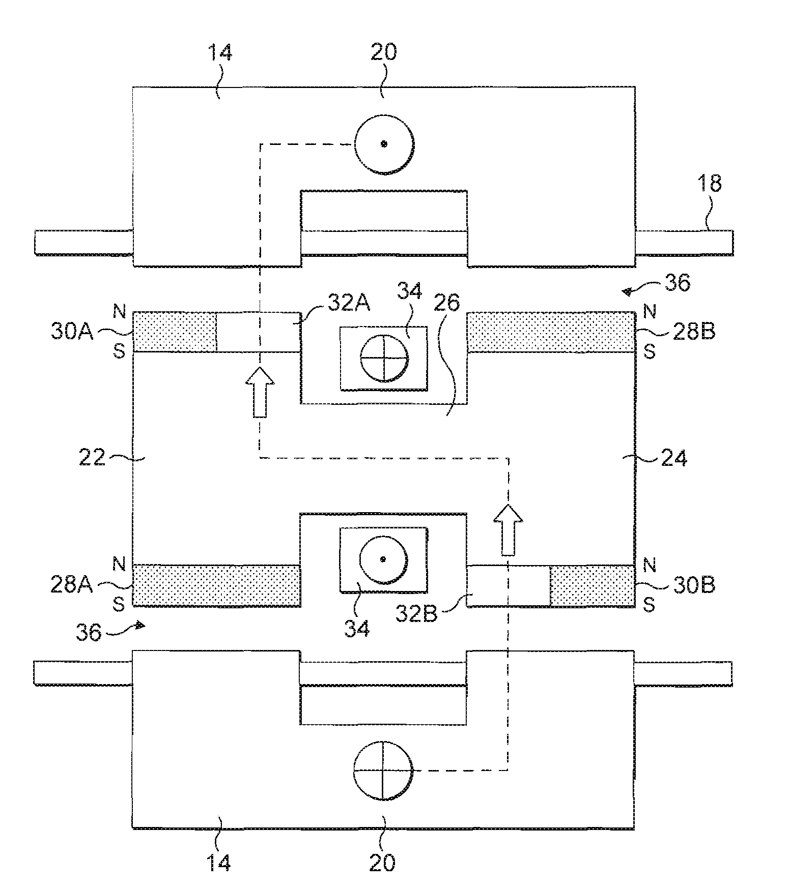
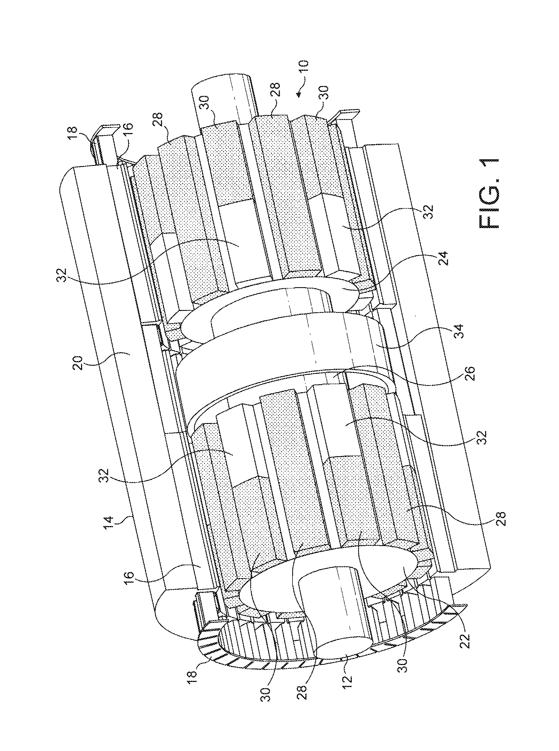
[0058]FIG. 1 shows parts of a rotating electrical machine in the invention. Referring to FIG. 1, the machine comprises a rotor assembly 10 mounted on a shaft 12, and located within a stator 14. In this embodiment the stator is cylindrical, and has a tubular chamber within which the rotor assembly rotates.

[0059]The stator 14 is formed from a plurality of laminated sheets of metal stacked together from left to right in FIG. 1. The majority of the laminations are provided with slotted teeth 16 which hold the stator windings 18. The exceptions are the laminations in a magnetic bridge 20 shown in the centre of the machine. These laminations are similar to the laminations elsewhere in the stator, but without the slot / teeth profiles of the other laminations. Once the laminated stator is formed the windings 18 are inserted, insulated and impregnated using conventional methods.

[0060]The rotor assembly 10 consists of a first rotor section 22, a second rotor section 24, and a rotating magnetic...

third embodiment

[0079]FIG. 9 shows parts of an electrical machine in the invention. Referring to FIG. 9, the machine comprises a rotor 50 located within a stator 52. As in the previous embodiments, the rotor is cylindrical, and rotates within a tubular chamber formed by the stator 52. The stator is laminated, and the rotor may be cast or laminated.

[0080]In the embodiment of FIG. 9, a plurality of permanent magnets 54 are embedded in recesses in the rotor 50. The permanent magnets are orientated such that their north-south axes lie in a circumferential direction within the rotor. Each alternate magnet faces in the opposite direction, such that each adjacent pair of magnets has either both south poles facing each other, or both north poles facing each other. The parts of the rotor between the permanent magnets act as ferrous poles 56, and are magnetised by the permanent magnets.

[0081]FIG. 10 shows a cross section through the electrical machine of FIG. 9. The flux paths within the machine are indicate...


PUM


Abstract

A rotating electrical machine is disclosed, the machine comprising a stator 14, 52 and a rotor 10, 50 arranged to rotate inside the stator. The rotor comprises a plurality of permanent magnets 28, 30, 54 arranged to produce a radial magnetic flux in an airgap between the rotor and the stator. The machine also comprises a stationary excitation coil 34, 46, 66. The rotor comprises a plurality of low reluctance elements 32, 58. A current through the stationary excitation coil causes a magnetic flux to be established in a magnetic flux path which passes into the rotor through a first low reluctance element and out of the rotor through a second low reluctance element, which magnetic flux combines with the radial magnetic flux produced by the permanent magnets in the airgap. This arrangement can allow control of the field within a permanent magnet radial flux machine.

Description

BACKGROUND TO THE INVENTION [0001]The present invention relates to rotating electrical machines, and in particular to rotating electrical machines having permanent magnets.[0002]Rotating electrical machines, such as motors and generators, generally comprise a rotor and a stator, which are arranged such that a magnetic flux is developed between the two. In a permanent magnet (PM) type machine, a number of permanent magnets are usually mounted on the rotor, while the stator is provided with stator windings. The permanent magnets cause a magnetic flux to flow across the air gap between the rotor and the stator. In the case of a generator, when the rotor is rotated by a prime mover, the rotating magnetic field causes an electrical current to flow in the stator windings, thereby generating the output power. In the case of a motor, an electrical current is supplied to the stator windings and the thus generated magnetic field causes the rotor to rotate.[0003]Permanent magnet type machines ...

Claims


Application Information

Patent Timeline
Patent Type & Authority Applications(United States)
IPC IPC(8): H02K21/04
CPCH02K21/046H02K1/2753H02K1/276H02K21/16
Inventor BROWN, NEIL
Owner CUMMINS GENERATOR TECH LTD
Why Eureka
Try Eureka