
Spirally conformable infusion catheter

a catheter and conformation technology, applied in the field of infusion catheters, can solve the problems of difficulty in adequately conforming to and delivering, and the coil may be too small to treat, and achieve the effect of convenient and convenient use, good contact and/or efficient delivery

Active Publication Date: 2010-01-21
TYCO HEALTHCARE GRP LP
View PDF39 Cites 23 Cited by
  • Summary
  • Abstract
  • Description
  • Claims
  • Application Information

AI Technical Summary

Benefits of technology

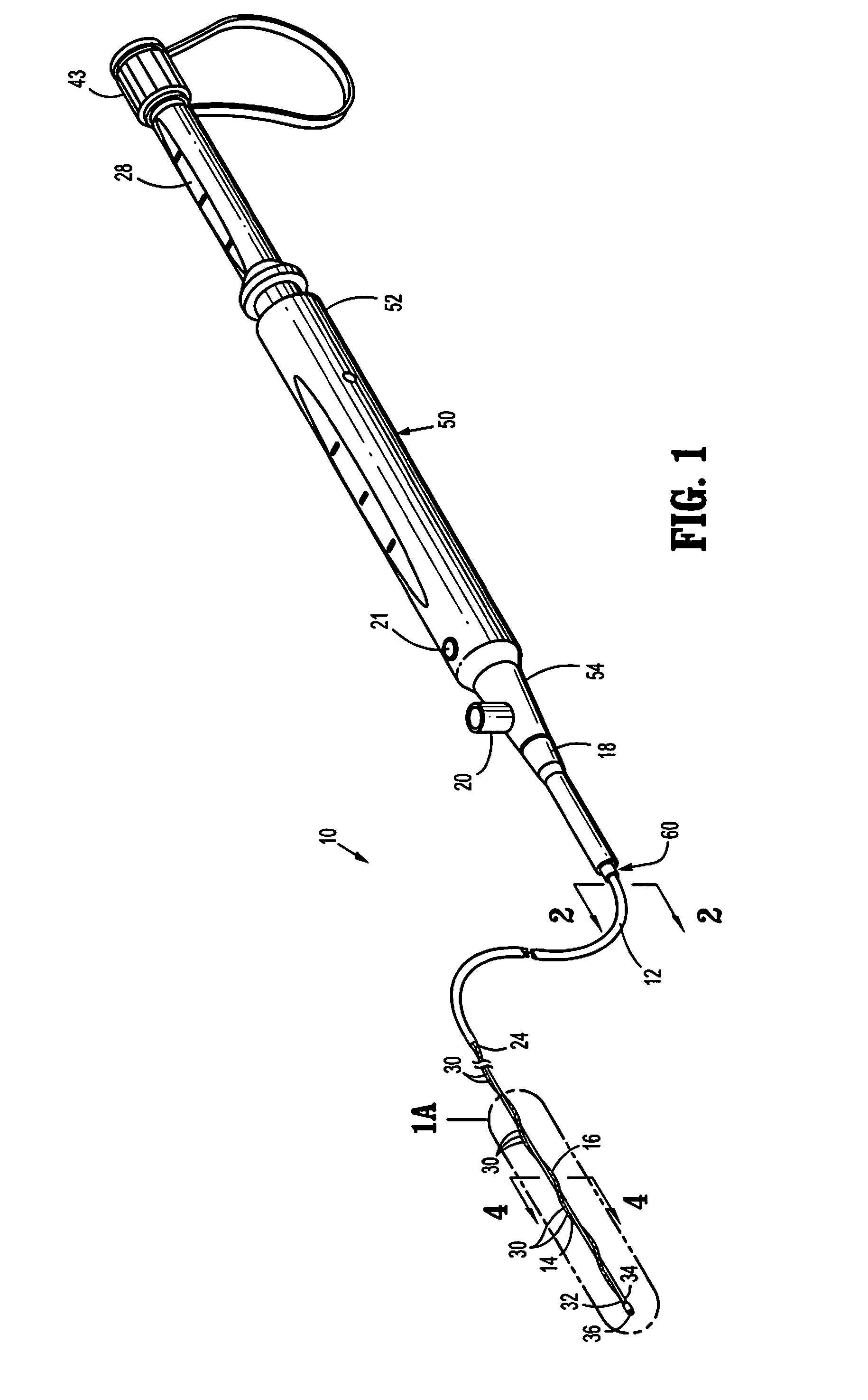
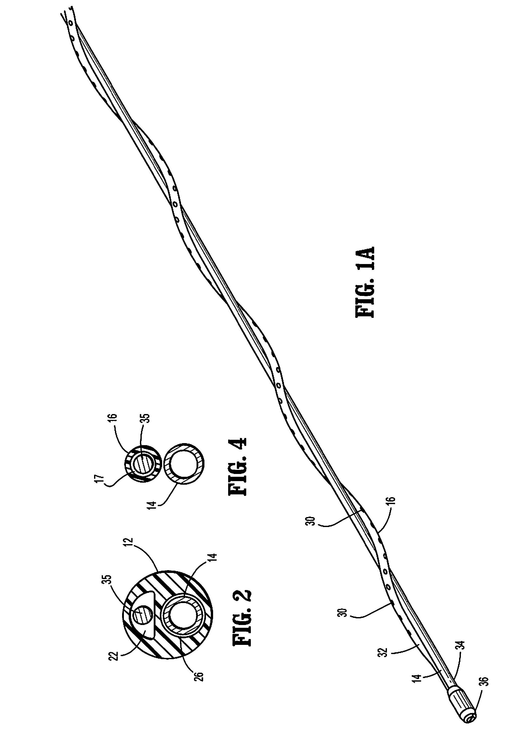
[0007]The central member has a distal end and a proximal end, where the distal end of the central member is connected to the distal end of the infusion tube. The proximal portion of the central member is slidably received in the second lumen of the catheter body. In this way, the central member may be axially advanced and retracted in order to lengthen and foreshorten the infusion tube, respectively. The infusion tube may be wrapped around the central member one or more times so that, when the central member is axially extended, the infusion tube will be closely positioned about the outer surface of the central member to facilitate insertion of the infusion catheter into a body lumen. Conversely, when the central member is axially retracted in the proximal direction, the infusion tube will expand radially outwardly. Advantageously, it has been found that the infusion tube will assume a generally helical or spiral configuration against the inner wall of the blood vessel or other body lumen in which it has been radially expanded. The helical or spiral configuration helps distribute the drug being delivered to the luminal wall being treated more uniformly in the radial direction.
[0009]In embodiments for the treatment of the peripheral vasculature, the infusion tube typically has a length in the range from about 1 cm to about 100 cm, and a width, typically an outer diameter, in the range from about 0.3 mm to about 2.8 mm. The catheter body, in turn, has a length in the range from about 5 cm to about 150 cm, and a width, typically an outer diameter, in the range from about 0.66 mm to about 4 mm, and the central member has a length in the range from about 10 cm to about 175 cm, and a width, typically a diameter, in the range from about 0.4 mm to about 3.7 mm. In still other embodiments, the infusion tube will have ports for releasing the substance, and the ports will be formed along its length. The ports may be spaced apart by distances in the range from about 2.5 mm to about 50 mm and may have width or diameter dimensions in the range from about 0.01 mm to about 0.25 mm. In still further specific embodiments, the ports may have variable spacing or porosity along the length of the infusion tube, in order to provide or improve uniform distribution.
[0011]As described above in connection with the apparatus of the present disclosure, the infusion tube will generally have a straight configuration, i.e. will have a certain elasticity which assumes a straight configuration when neither tension nor compression are being applied. The infusion tube may be helically wrapped, coiled or spiraled around the central member to provide for a more compact profile when the central member is in an advanced position. Alternatively, the infusion tube may be substantially axially aligned with the central member when the central member is in an advanced position. The infusion tube of the present disclosure is capable of conforming to regions of widely varying diameter within the body lumen to assure good contact and / or efficient delivery of the thrombolytic and other substances into the lumen. The structure of the present disclosure is also particularly useful for treating very long regions within a body lumen, typically regions extending from about 1 cm to about 100 cm within a peripheral vein.

Problems solved by technology

Although the benefits of such a pre-shaped coil are clearly evident, since the maximum diameter of the coil is fixed, the coil may be too small to treat relatively large blood vessels and may have difficulty in adequately conforming to and delivering thrombolytic and other agents throughout the length of the vessel to be treated especially in vessels of varying diameters.

Method used


Image

  • Spirally conformable infusion catheter
  • Spirally conformable infusion catheter
  • Spirally conformable infusion catheter

Examples


Embodiment Construction

[0024]Embodiments of the presently disclosed catheter assembly will now be described in detail with reference to the drawings wherein like reference numerals identify similar or identical elements in each of the several views. In the discussion that follows, the term “proximal” or “trailing” will refer to the portion of a structure that is closer to a user, while the term “distal” or “leading” will refer to the portion of the structure that is farther from the user. In addition, the term spiral as used in association with the infusion tube and the central member means that the infusion tube extends along and at least partially around the central member in a helical, coiled or like configuration.

[0025]Referring initially to FIGS. 1-4, a catheter assembly 10 constructed in accordance with the principles of the present disclosure includes a handle housing 50, a movable handle 28, a catheter body 12, a central member 14, and an infusion tube 16. Catheter body 12 extends at least partial...


PUM


Abstract

An infusion catheter includes a catheter body having a proximal end, a distal end, and two or more lumens extending therethrough. The infusion catheter also includes an infusion tube having a proximal end, a distal end, and one or more ports disposed therethrough. The first lumen of the catheter body is in fluid communication with the lumen of the infusion tube. A central member has a distal end connected to the distal end of the infusion tube, a proximal end, and a proximal portion slidably received in the second lumen of the catheter body. The infusion tube is disposed relative to the central member such that axial advancement of the central member relative to the catheter body radially collapses the infusion tube over the central member and axial retraction of the central member relative to the catheter body radially expands the infusion tube about the central member.

Description

CROSS-REFERENCE TO RELATED APPLICATION[0001]The present application claims the benefit of and priority to U.S. Provisional Patent Application Ser. No. 61 / 081,681 filed Jul. 17, 2008, which is incorporated herein by reference in its entirety.BACKGROUND[0002]1. Technical Field[0003]The present disclosure relates generally to medical devices and methods. More particularly, the present disclosure relates to an infusion catheter and methods for its use in delivering substances to vasculature.[0004]2. Description of the Related Art[0005]Catheters are used for delivering drugs through vasculature and other body lumens for a wide variety of purposes. It is often desirable to deliver thrombolytic and other substances to the peripheral vasculature, in particular the peripheral venous vasculature, in order to lyse and help remove clots in patients suffering from deep vein thrombosis (DVT) and other conditions. A number of catheters have been proposed for this purpose. For example, the catheter...

Claims


Application Information

Patent Timeline
IPC IPC(8): A61M5/14A61M25/00A61M25/09A61M25/098
CPCA61M25/0021A61M25/003A61M25/007A61M2025/0063A61M2025/0024A61M2025/0037A61M2025/0057A61M25/0102
Inventor THAI, MICHAELCHIEN, THOMASNING, KELVINMCRAE, ROBERT
Owner TYCO HEALTHCARE GRP LP
Learn More