Ratchet screwdriver with an accelerating structure

a screwdriver and accelerating technology, applied in screwdrivers, wrenches, manufacturing tools, etc., can solve the problems of lack of lower torque, inability to provide acceleration and orientation abilities, and inability to provide accuracy and convenience of operation

Inactive Publication Date: 2010-01-28
GONG FONG ENTERPRISE
View PDF6 Cites 21 Cited by
  • Summary
  • Abstract
  • Description
  • Claims
  • Application Information

AI Technical Summary

Benefits of technology

[0021]It is still a further object of the present invention to provide a ratchet screwdriver with a

Problems solved by technology

However, the conventional screwdriver is unable to provide abilities of acceleration and orientation.
But, it is unable to provide the accuracy and the convenience of operation.
However, it lacks of lower torque, high revolution output, neither does it has the convenience of operation concept, other than the above shortcomings, it is able to control deviation without the locating mean

Method used


Image

  • Ratchet screwdriver with an accelerating structure
  • Ratchet screwdriver with an accelerating structure
  • Ratchet screwdriver with an accelerating structure

Examples


Embodiment Construction

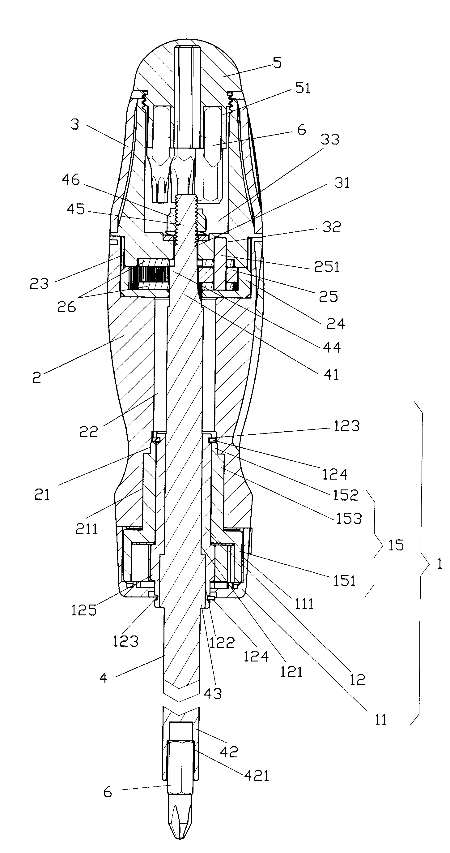
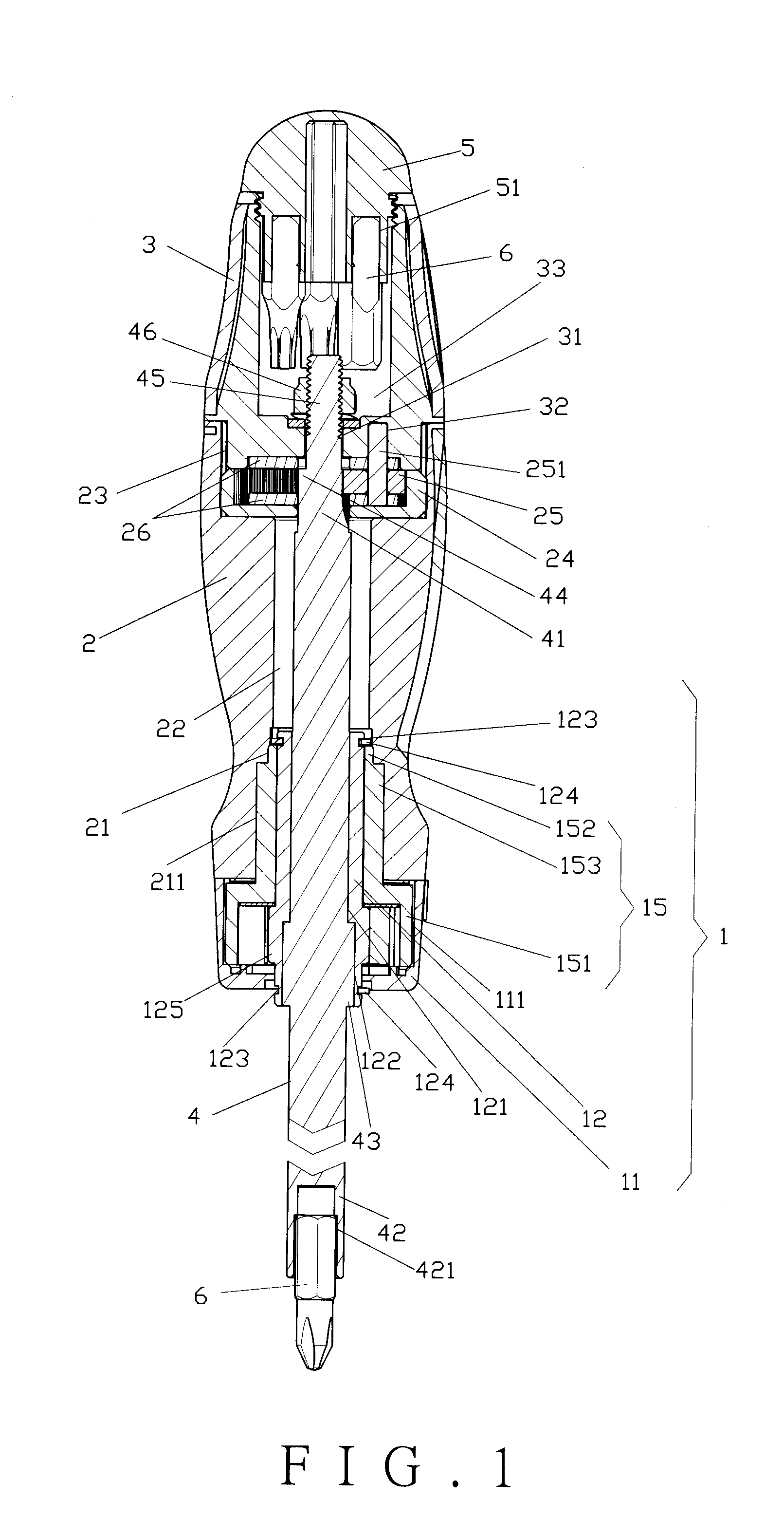
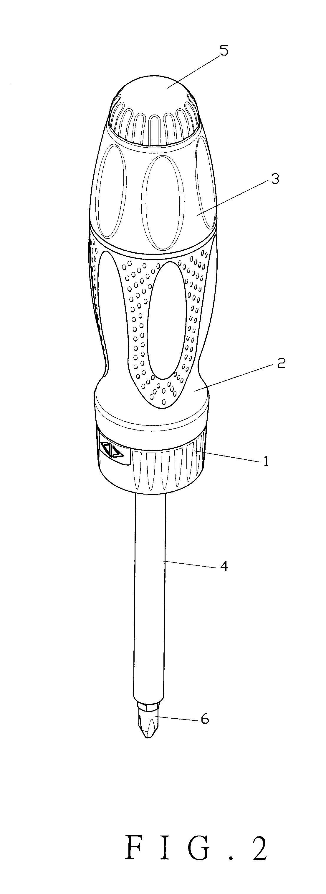
[0028]As shown in FIGS. 1 through 3, the present invention comprises a ratchet seat 1, a front handle 2, a rear handle 3, a sleeve connecting rod 4, and a tail cap 5.

[0029]The ratchet seat 1 comprises a barrel 11, a ratchet 12, two blocks 13, two springs 14, and a socket unit 15. The barrel 11 has a first chamber 111 therein. Two levers 112, the blocks 13 and the springs 14 are disposed in the first chamber 111. The ratchet 12 comprises a number of ratchet teeth 125 outwardly, a first through hole 121 and two slots 122. The two slots 122 are interconnected with the first through hole 121 and disposed at two opposite sides of the ratchet 12. The ratchet 12 further comprises a pair of circular grooves 123 and a pair of fasteners 124 at two ends thereof. The socket unit 15 comprises a nut 151 at one end and a sleeve 52 at the other end thereof. The nut 151 is inserted into the barrel 11. The sleeve 152 comprises protruding strips 153 outwardly. The fasteners 124 of the ratchet 12 are s...


PUM


Abstract

A ratchet screwdriver with an accelerating structure is provided, in particular to one combined a ratchet seat and a solar gear system. The ratchet seat controls the operating direction, and the solar gear system increases the output rpm for a user to choose high or low revolution to facilitate tightness or looseness of a screw.

Description

BACKGROUND OF THE INVENTION[0001]1. Field of the Invention[0002]The present invention relates to a ratchet screwdriver with an accelerating structure, and more particularly to one equipped with a ratchet seat and a solar gear system to facilitate operation.[0003]2. Description of the Prior Art[0004]A conventional screwdriver is used to tighten or loosen fasteners, such as screws or nuts. However, the conventional screwdriver is unable to provide abilities of acceleration and orientation.[0005]Taiwanese Patent Published No. 533956 disclosed a rotating structure for a precise screwdriver, which provides an accelerating function. But, it is unable to provide the accuracy and the convenience of operation.[0006]The above-mentioned patent has some shortcomings, such as:[0007]1. A solar gear structure can only increase the speed of tool, which is unable to change direction and locate its position.[0008]2. A lack of locating device will cause an inverse operation and decrease the speed.[000...

Claims


Application Information

Patent Timeline
IPC IPC(8): B25B15/04B25B13/46B25B17/00
CPCB25B15/04B25G1/085B25B17/00
Inventor HU, CHENG-TSAN
Owner GONG FONG ENTERPRISE
Why Eureka
Try Eureka