

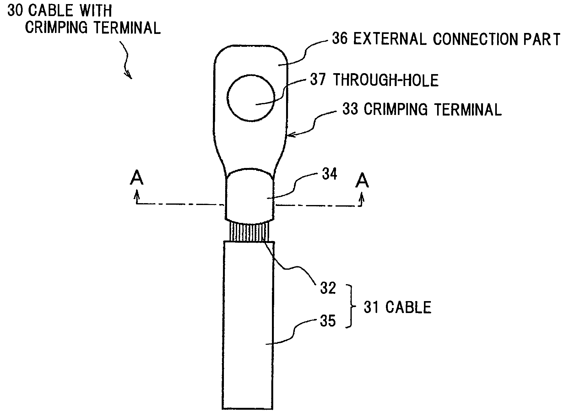
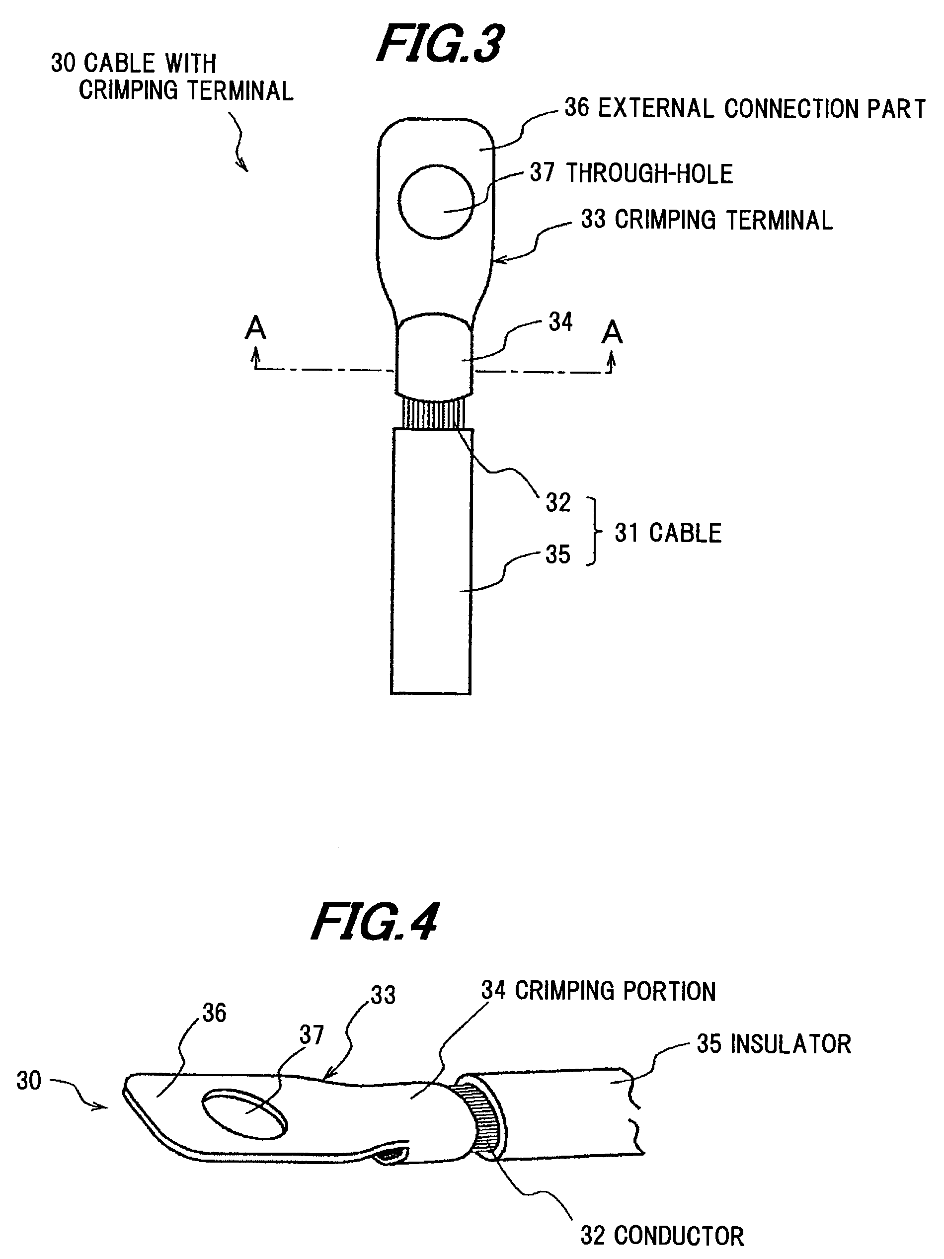
Cable with crimping terminal and method of making the same
a technology of crimping terminal and cable, which is applied in the direction of cable termination, coupling contact member, cable inlet sealing means, etc., can solve the problems of reducing the breaking strength of the crimping portion, difficult to apply the material to the cable, and difficult to obtain sufficient breaking strength, so as to suppress the decrease in breaking strength and increase the breaking strength
- Summary
- Abstract
- Description
- Claims
- Application Information
AI Technical Summary
Benefits of technology
Problems solved by technology
Method used
Image

Examples
examples 1 and 2
, Comparative Examples 1 and 2
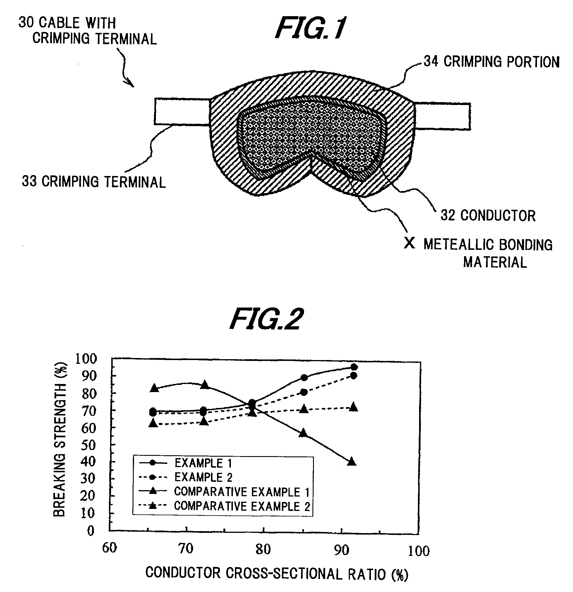
[0081]In order to confirm advantages of the invention, in four processes (Examples 1 and 2, and Comparative Examples 1 and 2), cable with crimping terminals were experimentally fabricated, and the breaking mode and the breaking strength at the respective crimping portions were compared.
[0082]In Example 1, the cable with crimping terminal 30 was used, which was fabricated by the method according to the invention (the method where the metallic bonding material which is obtained by sintering a bonding material in the form of a liquid or a paste where silver fine particles are dispersed in an organic solvent was used as the metallic bonding material X ), and in Example 2, the cable with crimping terminal 30 was used, which was subjected to a shelf test at high temperature after being fabricated according to the method of the invention.
[0083]In Comparative Example 1, the cable with crimping terminal 30 was used, which was fabricated by the conventional metho...
example 12
[0102]Next, evaluation was carried out with regard to the cable with crimping terminal (Example 12) fabricated by using the crimping terminal 33 and the conductor 32 which were coated with metals plating other than tin plating.
[0103]In each case that the crimping terminals 33 were used, which were coated with silver, nickel and copper plating, even if the surface materials (plating materials) of the conductor 32 were changed to silver, nickel, copper and tin, the breaking strength almost equal to that of Example 1 could be obtained.
[0104]Similarly, in case that the surface materials of the crimping terminals 33 was tin, even if the surface materials of the conductor 32 were changed to silver, nickel and copper, the breaking strength almost equal to that of Example 1 could be obtained.
[0105]From the above facts, it is known that by connecting the conductor of the cable and the crimping terminal via the metallic bonding material X, the breaking strength just after the crimping connect...
PUM
| Property | Measurement | Unit |
|---|---|---|
| particle size | aaaaa | aaaaa |
| particle size | aaaaa | aaaaa |
| particle size | aaaaa | aaaaa |
Abstract
Description
Claims
Application Information