Radiographic imaging system

a radiographic imaging and system technology, applied in the field of radiographic imaging systems, can solve the problems of affecting the progress affecting the quality of the imaging session, and taking a longer time than normal imaging, so as to reduce the psychological burden or anxiety of the examin

Active Publication Date: 2010-01-28
FUJIFILM CORP
View PDF4 Cites 16 Cited by
  • Summary
  • Abstract
  • Description
  • Claims
  • Application Information

AI Technical Summary

Benefits of technology

[0021]An object of the present invention is to solve the above problems associated with the prior art and provide a radiographic imaging system that allows the examinee (patient) to know the progress of an imaging session, such as a remaining number of images to be taken out of the series of images and a remaining imaging time in the imaging session for taking the series of images, in long region imaging, tomosynthesis imaging, or the like where images of the examinee are successively taken by a radiographic imaging system having functions of successively taking a series of images, thereby reducing a psychological burden or an anxiety on the part of the examinee.

Problems solved by technology

Naturally, imaging methods as exemplified by long region imaging and tomosynthesis imaging, where a series of images are taken successively, take a longer time than normal imaging.
However, in an imaging session such as long region imaging wherein a series of images are successively taken, the examinee is ignorant when the imaging session will end.
In addition, in the conventional radiographic imaging system, while the operator can be aware of the state of the system and the progress of the imaging session, the examinee remains ignorant of the progress of the imaging session.
Such conditions where the examinee is left ignorant of the length of time it will take to complete the imaging session and of the progress thereof and required to wait motionlessly causes anxiety to and produces psychological burden on the part of the examinee.
In particular, where the examinee is an elderly person or an individual with disabilities or where the examinee has suffered an injury such as a bone fracture, the examinee will feel a significantly great anxiety or psychological burden when he / she is required to hold still patiently even for a short period of time.

Method used


Image

  • Radiographic imaging system
  • Radiographic imaging system
  • Radiographic imaging system

Examples


Embodiment Construction

[0025]Now, the radiographic imaging system of the invention will be described in detail referring to a preferred embodiment illustrated in the attached drawings.

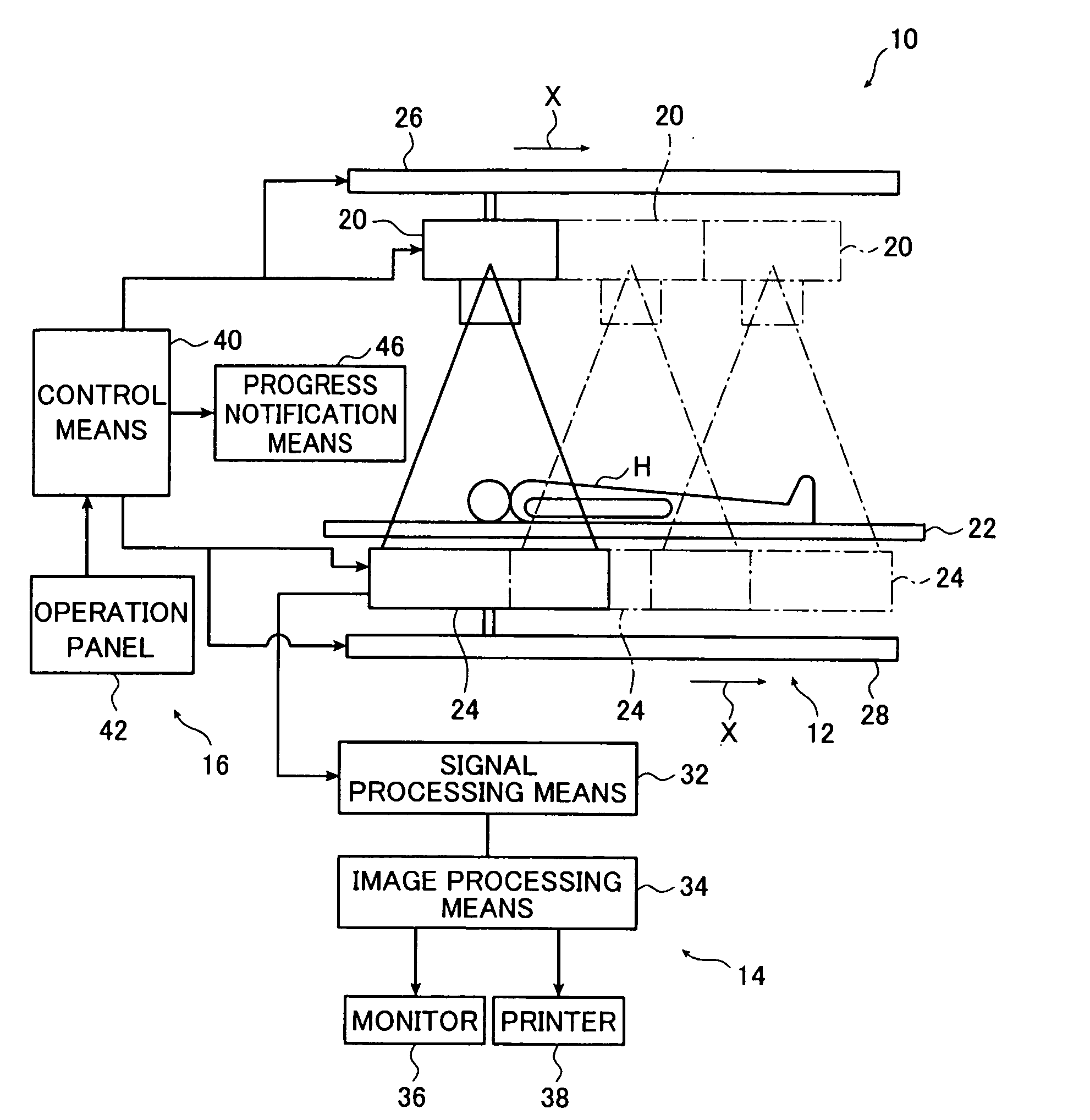
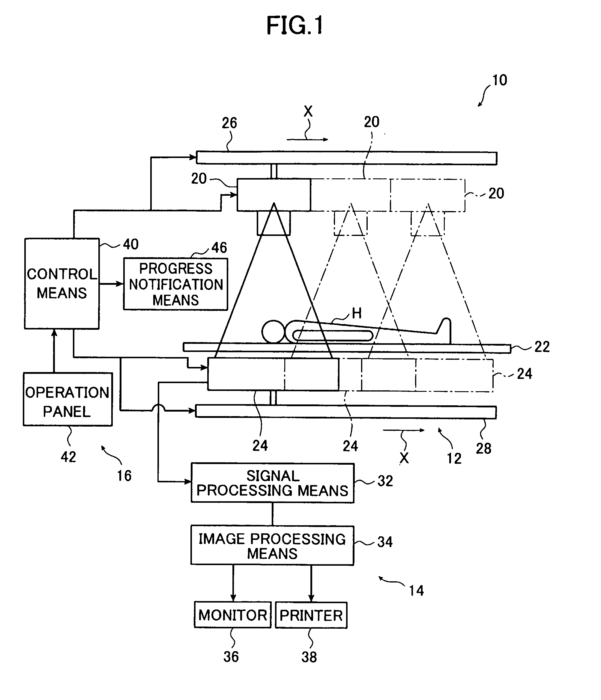
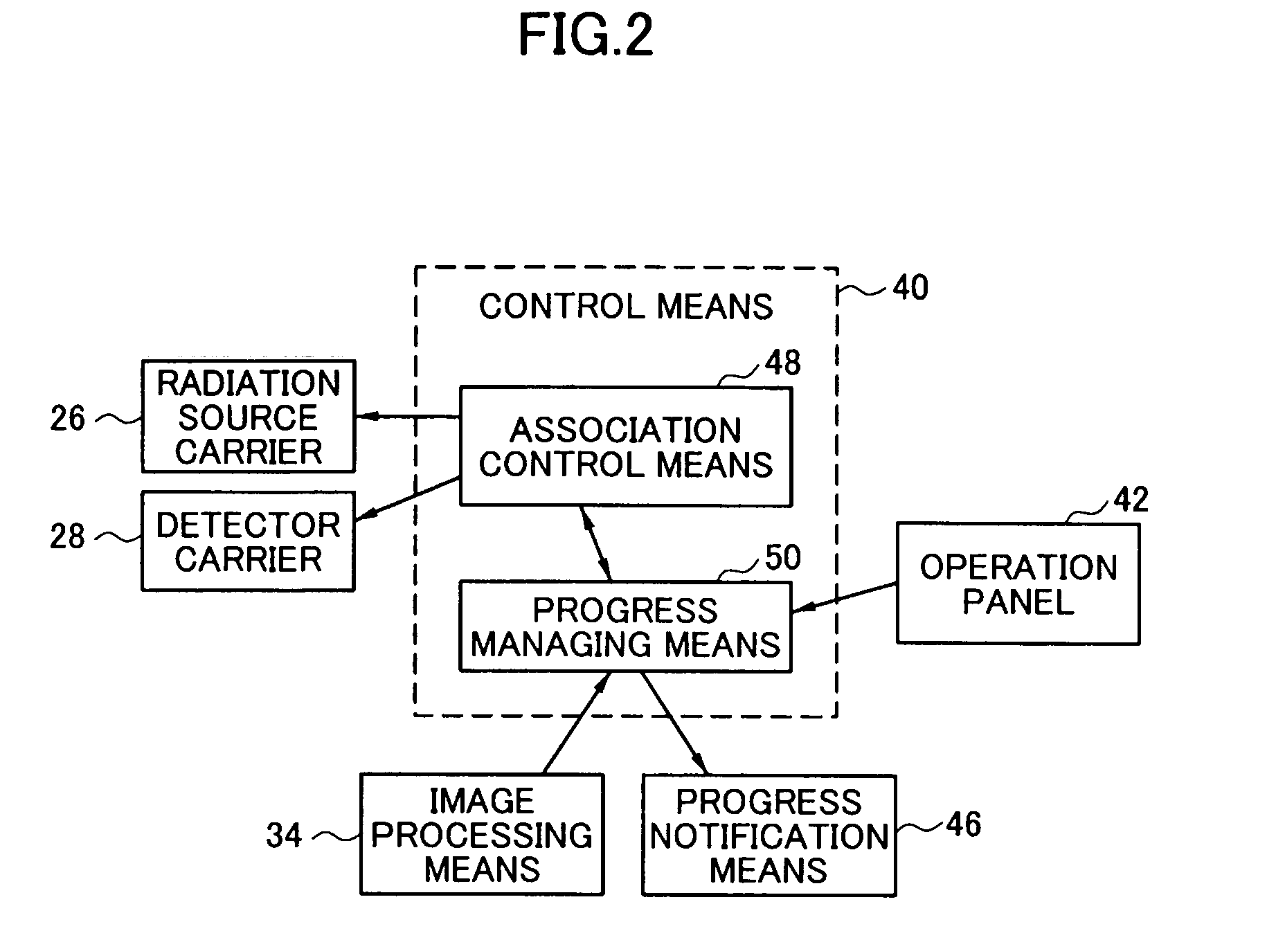
[0026]FIG. 1 schematically illustrates a radiographic imaging system 10 according to one embodiment of the invention. The radiographic imaging system 10 causes radiation to penetrate an examinee H, causes a radiation detector 24 to detect the radiation having penetrated the examinee H, and processes image data of a radiographic image thus acquired to produce a radiographic image of the examinee H. The radiographic imaging system 10 comprises an imaging unit 12, data processing / output unit 14 and a control unit 16.

[0027]Note that the imaging system 10 is also capable of long region imaging in addition to normal imaging where a radiographic image of the examinee H, asked to stay motionless, is taken by a single exposure. The long region imaging will be described later in detail.

[0028]The imaging unit 12 takes a radiographic im...


PUM

PropertyMeasurementUnit
radiographic imagingaaaaaaaaaa
imaging timeaaaaaaaaaa
long region imagingaaaaaaaaaa

Abstract

A radiographic imaging system comprises: a radiation source for irradiating an examinee with radiation; a radiation detector for detecting radiation that has penetrated the examinee to acquire radiographic image data; image data receiving unit for receiving the radiographic image data from the radiation detector and outputting a termination signal indicating that an image has been taken each time receiving the radiographic image data; control unit for controlling operations of the radiation source and the radiation detector and detecting a progress of an imaging session for successively taking a series of images according to the termination signal outputted from the image data receiving unit; and progress notification unit for notifying the examinee of a progress of imaging session detected by the control unit.

Description

BACKGROUND OF THE INVENTION[0001]The present invention relates to a radiographic imaging system for taking a radiographic image of an examinee and more particularly to a radiographic imaging system whereby the examinee is allowed to know the progress of imaging session as in long region imaging where a series of successive images are taken.[0002]A radiographic image detector has been conventionally used in medicine to produce diagnostic images or in industry to conduct nondestructive tests. The radiographic image detector converts radiation that has penetrated a subject into an electric signal to achieve radiographic imaging. The radiation here includes X-ray, alpha ray, beta ray, gamma ray, electron beam, and ultraviolet ray.[0003]The radiographic image detector is exemplified by a solid state radiation detector, i.e., so-called a flat panel detector hereinafter referred to as FPD, which converts radiation into an electric image signal, and an X-ray image tube that converts a radio...

Claims


Application Information

Patent Timeline
Patent Type & Authority Applications(United States)
IPC IPC(8): G01N23/04
CPCA61B6/4233A61B6/5241A61B6/5229A61B6/46
Inventor AKAHORI, SADATO
Owner FUJIFILM CORP
Why Eureka
Try Eureka