Grinding tool and method for fabricating the same

Inactive Publication Date: 2010-01-28
KINIK
View PDF7 Cites 39 Cited by
  • Summary
  • Abstract
  • Description
  • Claims
  • Application Information

AI Technical Summary

Benefits of technology

[0024]Accordingly, by the method for fabricating a grinding tool according to the present invention, the height of the abrasive particles can be precisely controlled, and thereby each of the abrasive particles can efficiently perform machining so as to enhance the machining efficiency and precision of the grinding tool. Meanwhile, the method according to the present invention can resolve the matter of deformation due to the shrinkage differences. In addition, the method provided by the present invention can inhibit the precision errors caused by the thermal deformation of the backplane, and thus more kinds of

Problems solved by technology

Thereby, it is an important issue to develop various grinding tools that can meet process requirements.
However, for conventional grinding tools, some disadvantages need to be improved, such as, the poor adhesion and non-uniform distribution of abrasive particles on a substrate.
However, in such a high-temperature process, the substrate will suffer from heat deformation.
Accordingly, it is necessary to use a material with low heat deformation characteristics as the substrate, and thereby the selection of the substrate becomes more difficult and the precision of the resultant grinding tool cannot be controlled well.
However, if the abrasive particles are attached to the substrate by a binder, the precision of the working surface of the resultant product

Method used


Image

  • Grinding tool and method for fabricating the same
  • Grinding tool and method for fabricating the same
  • Grinding tool and method for fabricating the same

Examples


embodiment 1

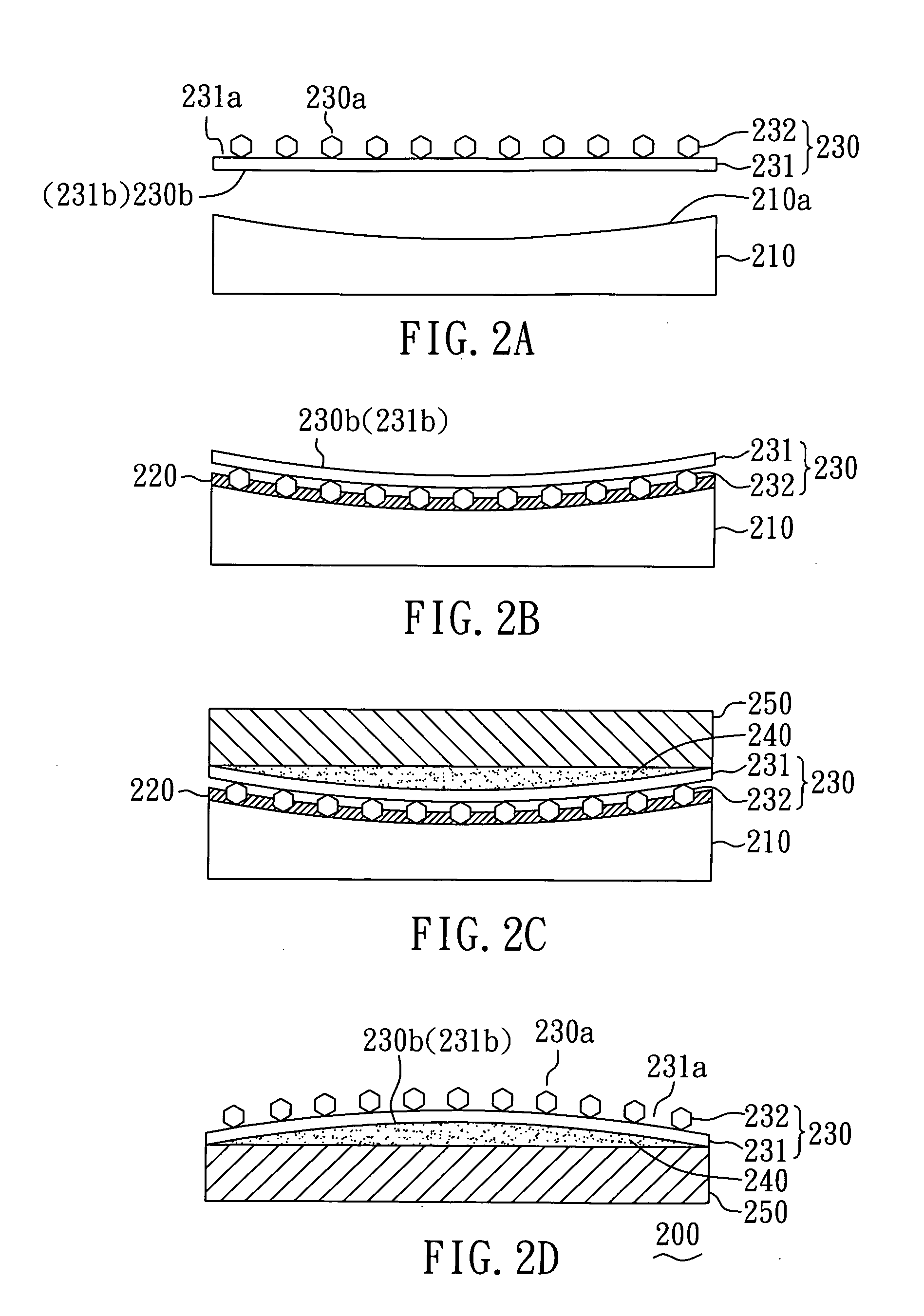
[0030]With reference to FIGS. 2A to 2D, there is shown a process for fabricating a grinding tool according to a preferred embodiment of the present invention.

[0031]As shown in FIG. 2A, a grinding plate 230 having a working surface 230a and a non-working surface 230b and a mold 210 with an adjustment surface 210a are first provided. Herein, the grinding plate 230 comprises: a soft substrate 231 having a working surface 231a and a non-working surface 231b and a plurality of abrasive particles 232 formed on the working surface 231a of the soft substrate 231 by brazing.

[0032]Subsequently, as shown in FIG. 2B, the adjustment surface of the mold 210 is coated with a binder 220, and then the working surface of the grinding plate 230 is attached and fits precisely on the adjustment surface of the mold 210, so that the abrasive particles 232 on the working surface of the grinding plate 230 can fit precisely on the adjustment surface of the mold 210. Next, the binder 220 is cured by a heating...

embodiment 2

[0038]With reference to FIGS. 3A to 3D, there is shown a process for fabricating a grinding tool according to a preferred embodiment of the present invention. The manufacturing process provided by the present embodiment is the same as that described in Embodiment 1, except that the present embodiment uses a grinding plate with abrasive particles formed on two surfaces thereof and a mold with a flat adjustment surface.

[0039]As shown in FIG. 3A, a grinding plate 330 having a working surface 330a and a non-working surface 330b and a mold 310 with an adjustment surface 310a are first provided. Herein, the grinding plate 330 comprises: a soft substrate 231 having a working surface 231a and a non-working surface 231b and a plurality of abrasive particles 232 formed on the working surface 231a and the non-working surface 231b of the soft substrate 231 by brazing. In the present embodiment, the deformation resulting from the difference of shrinkage between the two surfaces of the soft subst...

embodiment 3

[0046]With reference to FIGS. 4A to 4D, there is shown a process for fabricating a grinding tool according to a preferred embodiment of the present invention. The manufacturing process provided by the present embodiment is the same as that described in Embodiment 1, except that the grinding player used in the present embodiment further comprises a combining layer.

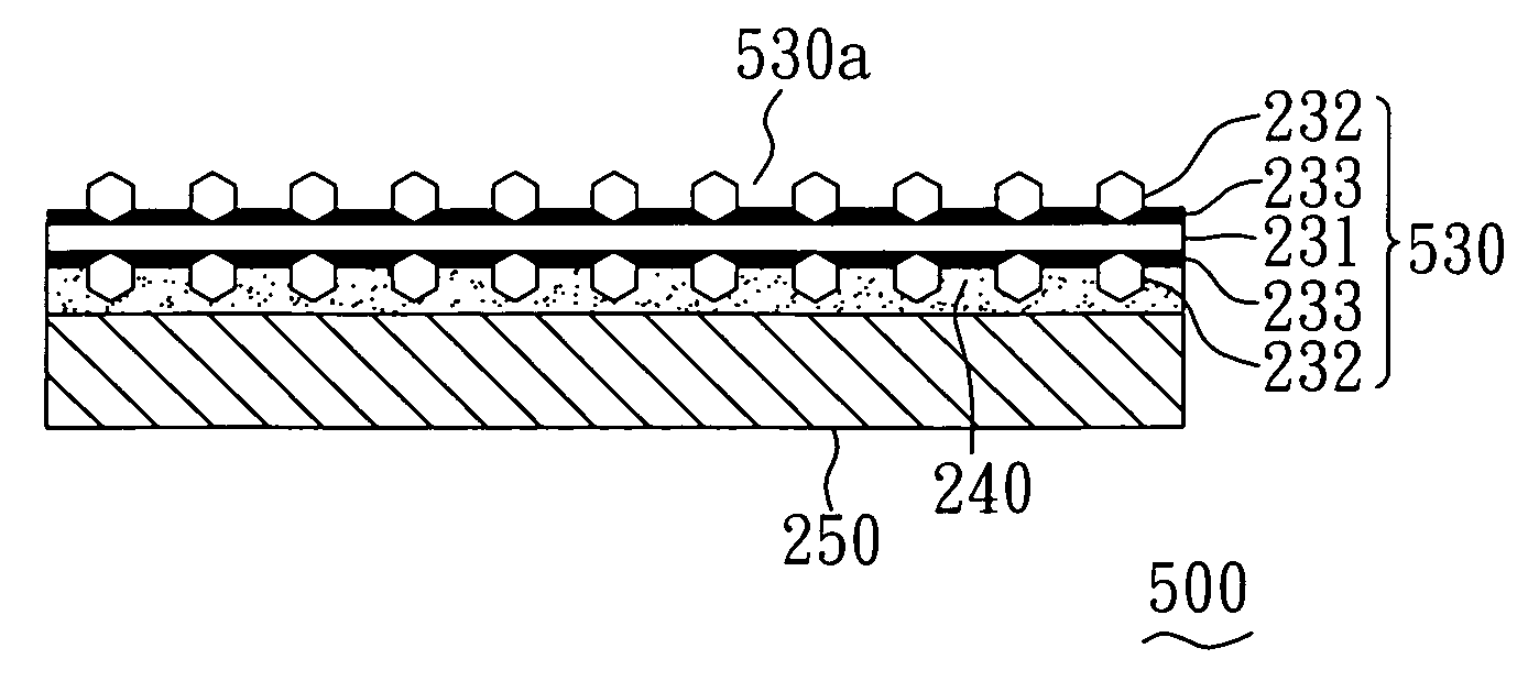
[0047]As shown in FIG. 4A, a grinding plate 430 having a working surface 430a and a non-working surface 430b and a mold 210 with an adjustment surface 210a are first provided. Herein, the grinding plate 430 comprises: a soft substrate 231 having a working surface 231a and a non-working surface 231b; a combining layer 233 formed on the working surface 231a of the soft substrate 231; and a plurality of abrasive particles 232 formed on the surface of the combining layer 233 (in the present embodiment, the combining layer 233 is a metal layer) by brazing of metals.

[0048]Subsequently, as shown in FIG. 4B, the adjustment surface ...


PUM

PropertyMeasurementUnit
Thicknessaaaaaaaaaa
Thicknessaaaaaaaaaa
Diameteraaaaaaaaaa

Abstract

The present invention relates to a grinding tool and a method for fabricating the same. The method comprises: (A) providing a grinding plate having a working surface and a non-working surface, a mold having an adjustment surface, and a backplane; (B) getting the working surface of the grinding plate to fit precisely and be retained on the adjustment surface of the mold by a binder; (C) forming an adhesive layer on the non-working surface of the grinding plate; (D) disposing the backplane on a surface of the adhesive layer to retain the backplane over the non-working surface of the grinding plate by the adhesive layer; and (E) removing the binder to separate the mold from the grinding plate. Accordingly, the present invention can significantly improve the precision and lifetime of products, reduce the cost of production, and enhance the machining efficiency.

Description

BACKGROUND OF THE INVENTION[0001]1. Field of the Invention[0002]The present invention relates to a grinding tool and a method for fabricating the same and, more particularly, to a grinding tool and a method for fabricating the same that can improve the precision and lifetime of products, reduce the cost of production, and enhance the machining efficiency.[0003]2. Description of Related Art[0004]Grinding and polishing are ultra-precision machining technologies with the ability to make the surface of a workpiece have acceptable smoothness and flatness. Accordingly, grinding and polishing are widely used in precision machining of the surface of an object, such as hard and brittle metals, ceramics, glass and wafers. Thereby, it is an important issue to develop various grinding tools that can meet process requirements.[0005]The manufacture and usage of grinding tools have been developed over many years. However, for conventional grinding tools, some disadvantages need to be improved, suc...

Claims


Application Information

Patent Timeline
IPC IPC(8): B23F21/02B24D11/00
CPCB24D3/002B24D18/0009B24D11/001
Inventor CHOU, JUI-LINLIAO, TUNG-LIANGCHEN, YUNG-CHUAN
Owner KINIK
Why Eureka
Try Eureka