Clean room

a technology for cleaning rooms and rooms, applied in lighting and heating apparatus, ventilation systems, heating types, etc., can solve the problems of abnormal heat generation or burning, short circuit, and inability to meet the necessary quality required for wafers or sufficient productivity, and achieve the effect of preventing pollutants from dropping and low cos

Inactive Publication Date: 2010-01-28
PANASONIC CORP
View PDF8 Cites 13 Cited by
  • Summary
  • Abstract
  • Description
  • Claims
  • Application Information

AI Technical Summary

Benefits of technology

[0051]As described above, in the clean room of the present invention, an ascending air flow rising from the top face of the heat radiating member due to heat generation of the heat radiating member is guided to flow outward from the gap between the dust-exhaust acceleration face of the dust-exhaust assistant member and the top face of the heat radiating member, by the dust-exhaust acceleration face of the dust-exhaust assistant member. Consequently, pollutants, such as dusts and chemical substances, generated on the upper portion of the heat radiating member or on the periphery thereof, are discharged outward from the gap together with the ascending air flow, thereby making it possible to effectively prevent the pollutants from dropping onto the top face of the heat radiating member. That is, by optimizing ascending air flows caused by whirling air flows or thermal convections generated on the upper portion of each of the heat radiating members, such as various IC manufacturing devices or various kinds of inspection devices, it becomes possible to prevent pollutants, such as dusts and chemical substances, from falling onto a wafer that is a subject to be processed in the heat radiating member, and adhering thereto.
[0052]Moreover, in a case where the dust-exhaust assistant member is made of a simple box or air packing, it is possible to eliminate the necessity of carrying out a large-scale construction work on the ceiling face, and also to install the dust-exhaust assistant member on the ceiling without the necessity of stopping the production activities; thus, it becomes possible to achieve low costs, and also to control the production conditions and environmental conditions, such as cleanliness factor or temperature / moisture degree, to higher levels.

Problems solved by technology

Consequently, the concentration of dusts, chemical substances, or the like in the air increases, with the result that gigantic sizes or weight increases due to collision among dusts, chemical substances, or the like cause the dusts or chemical substances or the like to freely fall down finally to adhere onto a wafer manufactured in the heat radiating member 110, failing to satisfy necessary quality required for the wafer or sufficient productivity thereof.
At present, the wiring pattern pitch on the wafer is about 50 nanometers, which corresponds to a ultra fine structure, and when pollutants such as dusts or chemical substances having a size larger than the wiring pattern pitch fall on the wafer, the wafer tends to be short-circuited by the pollutants, such as dusts or chemical substances, to cause an abnormal heat generation or burning.

Method used


Image

  • Clean room
  • Clean room
  • Clean room

Examples


working example 1

[0104]Referring to drawings, the following description will explain specific working examples of the embodiments of the present invention.

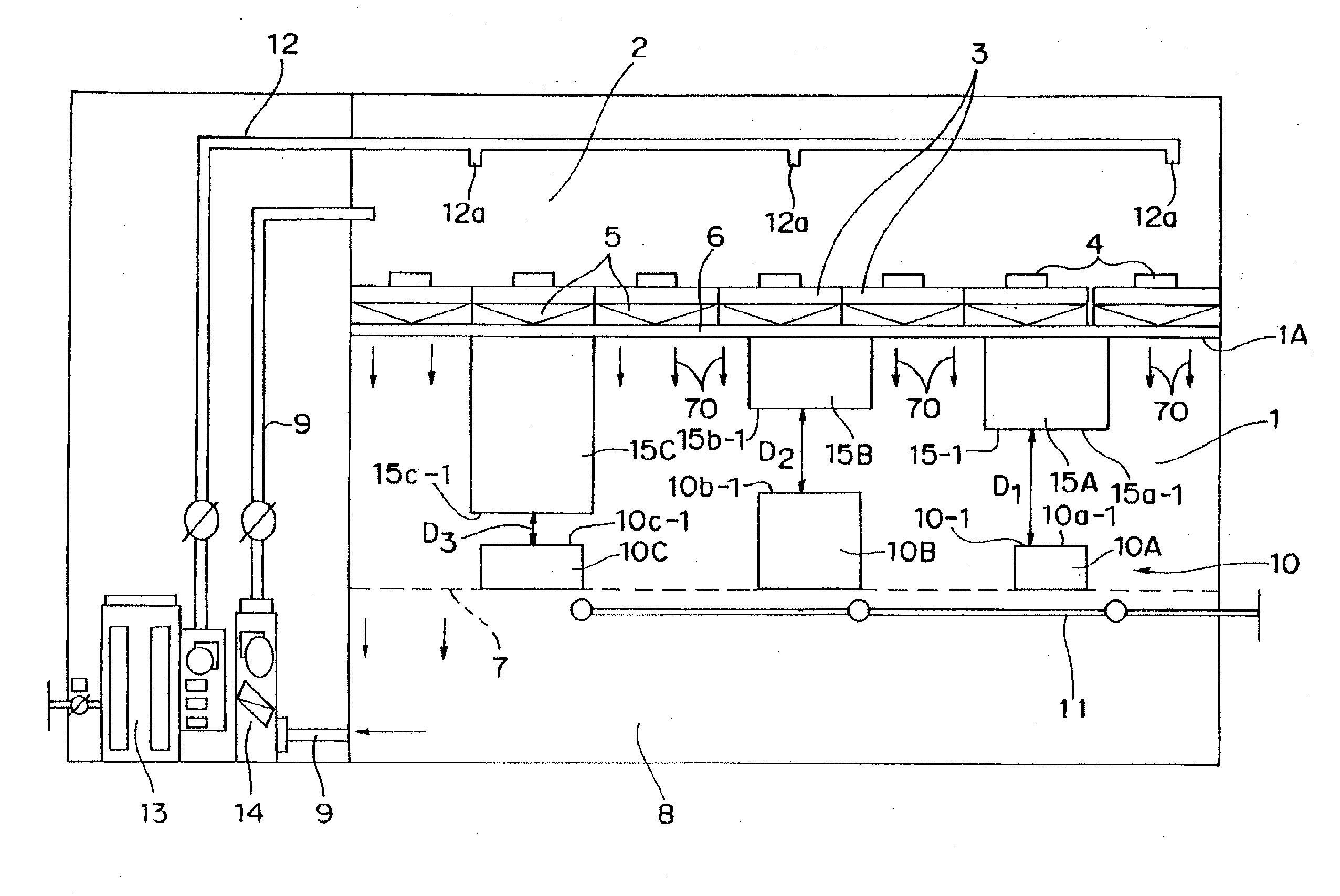
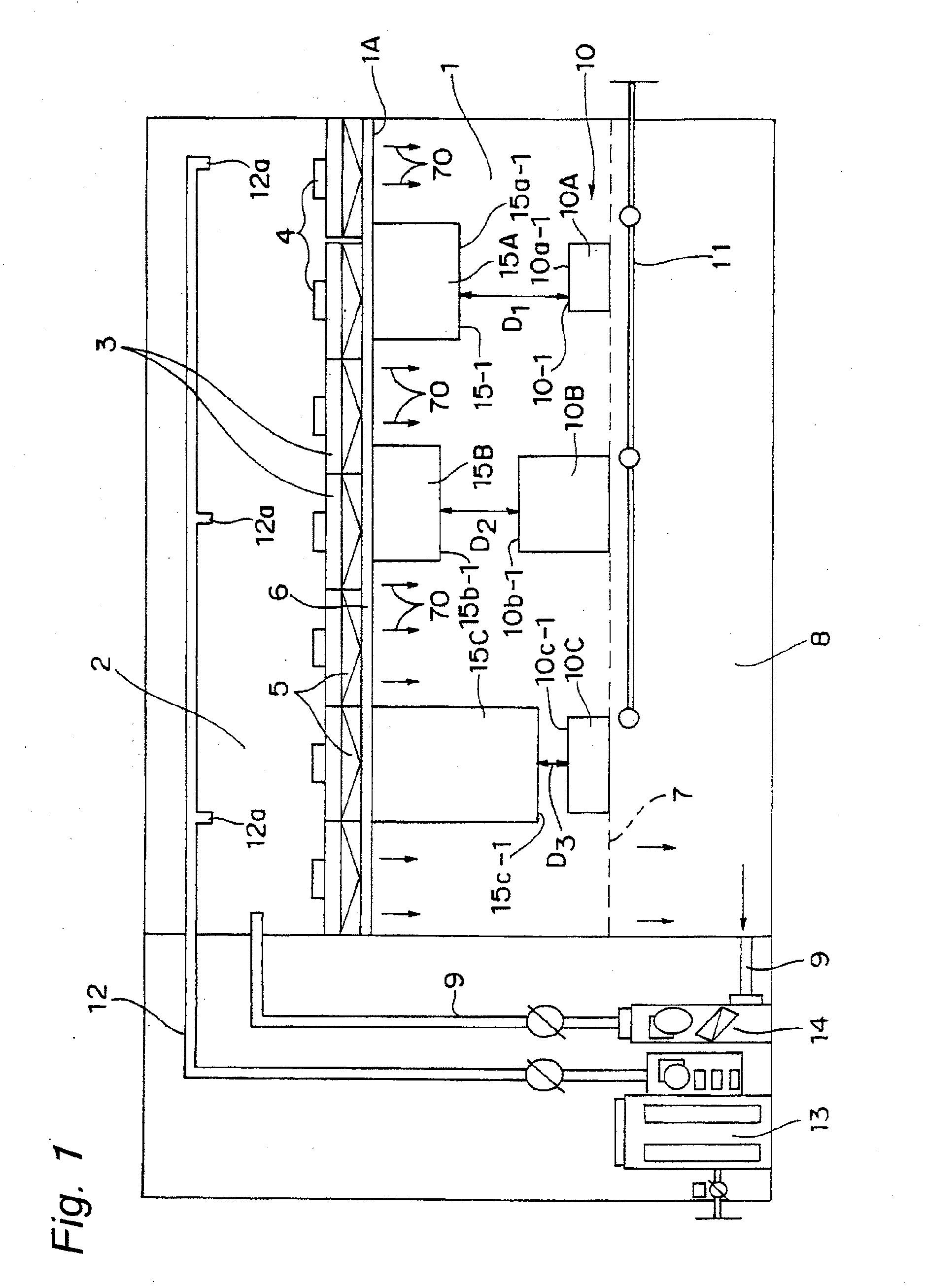
[0105]A clean room serving as working example 1, as shown in FIG. 1, is provided with a clean chamber 1 serving as an industrial clean room, that has a height of 3.5 m, a ceiling room 2 having a height of 3 m, and an under floor room 8 having a height of 2.5 m, and has a size of 12 m in the lateral direction and 10 m in the depth direction. Moreover, a grating floor 7 having an open efficiency of 45% is adopted therein.

[0106]The clean room relating to working example 1 that embodies the present invention is mainly used as a semiconductor manufacturing room and a semiconductor inspection room, and in order to maintain the managing temperature of machine and inspection areas in a range from 23±0.5° C., the managing moisture to 50%, the managing cleanliness factor to JIS class 1 or less (class 10 or less in ISO standard) and the managing cleanliness ...

working example 2

[0113]In the same structure as that of working example 1, the second heat radiating member 10B of FIG. 1 is a device used as a semiconductor dry etching device, and the shape of the second heat radiating member 10B has a height of 1.5 m, with longitudinal and lateral widths being set to 1 m, and the power supply capacity thereof is 12500 W / h. The surface temperature Tb of the top face 10b-1 of the second heat radiating member 10B was measured by a contact-type temperature made by Testo K.K. in the same manner, with the result that the surface temperature Tb of the top face 10b-1 varied from 73° C. to 99° C., depending on the semiconductor etching state carried out on the second heat radiating member 10B or the number of wafers to be processed therefor, with a temperature difference (Tb−Te)=ΔT of the clean chamber 1 from the ambient temperature Te being about 50° C. to 75° C.

[0114]A transparent box (1.5 m in longitudinal length×1.5 m in lateral length×0.7 m in height) was formed betw...

working example 3

[0117]In the same structure as that of working example 1, the third heat radiating member 10A of FIG. 1 is a device used as a semiconductor diffusion furnace, and the shape of the third heat radiating member 10A has a cubic shape (rectangular parallelepiped) having each side of 1 m, and the power supply capacity thereof is 42500 W / h. The surface temperature of the top face 10a-1 of the third heat radiating member 10A was measured by a contact-type temperature made by Testo K.K. in the same manner, with the result that the surface temperature Ta of the top face 10a-1 varied from 93° C. to 130° C., depending on the semiconductor heating treatment state carried out on the third heat radiating member 10A or the number of wafers to be processed therefor, with a temperature difference (Ta−Te)=ΔT of the clean chamber 1 from the ambient temperature Te being about 75° C. to 100° C.

[0118]A transparent box (1.5 m in longitudinal length×1.5 m in lateral length×0.8 m in height) was formed betwee...


PUM


Abstract

A dust-exhaust acceleration face of a dust-exhaust assistant member is disposed so as to face a top face of a heat radiating member of a production facility or the like so that a gap between the top face of the heat radiating member and the dust-exhaust acceleration face of the dust-exhaust assistant member is occupied by ascending air flows, each having a falling velocity (terminal velocity) that is not accelerated beyond a fixed velocity, to form a balanced state between the size of an object, such as a dust particulate or a chemical substance particulate, and air resistance when the object is freely falling in the air; thus, the object, such as a dust particulate and a chemical substance particulate, is prevented from falling onto the heat radiating member.

Description

TECHNICAL FIELD[0001]The present invention relates to a clean room that is used for a non-dust room or a sterile room in a semiconductor manufacturing factory, a FPD (Flat Panel Display) manufacturing factory, a precision machine factory, a chemicals manufacturing factory, and the like.BACKGROUND ART[0002]In a semiconductor factory or a FPD manufacturing factory, along with the developments of highly integrated devices, there have been strong demands for controlling environmental conditions, such as a cleanliness factor or temperature and moisture degrees, in high levels. Moreover, because of recent severe cost competitions in semiconductors or FPDs, there have been demands for reducing the construction cost of a clean room, that is, initial costs, and running costs of the clean room itself.[0003]A full-face down flowing system, as shown in FIG. 29, has been proposed as a system for achieving a clean room having a high cleanliness factor. In this system, the air inside a ceiling cha...

Claims


Application Information

Patent Timeline
Patent Type & Authority Applications(United States)
IPC IPC(8): B01L1/04
CPCH01L21/67115F24F3/161F24F3/167F24F7/06F24F7/10
Inventor UEMATSU, KATSUHITOMATSUDA, NAOKONAKA, HIROYUKI
Owner PANASONIC CORP
Why Eureka
Try Eureka