
Non-Invasive Method And Device For Measuring Cardiac Output

Inactive Publication Date: 2010-01-28
SARCOS LC
View PDF77 Cites 18 Cited by
  • Summary
  • Abstract
  • Description
  • Claims
  • Application Information

AI Technical Summary

Benefits of technology

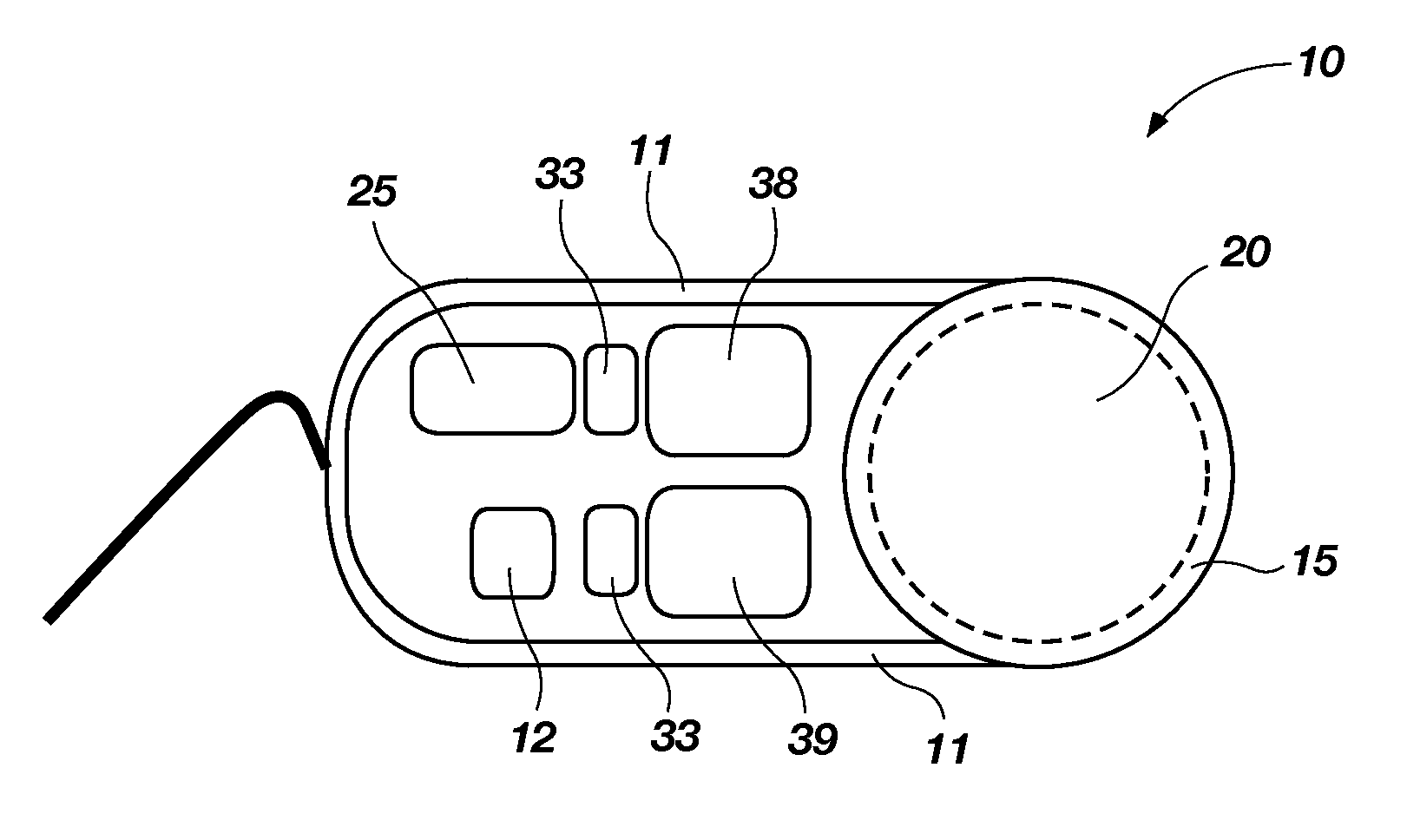
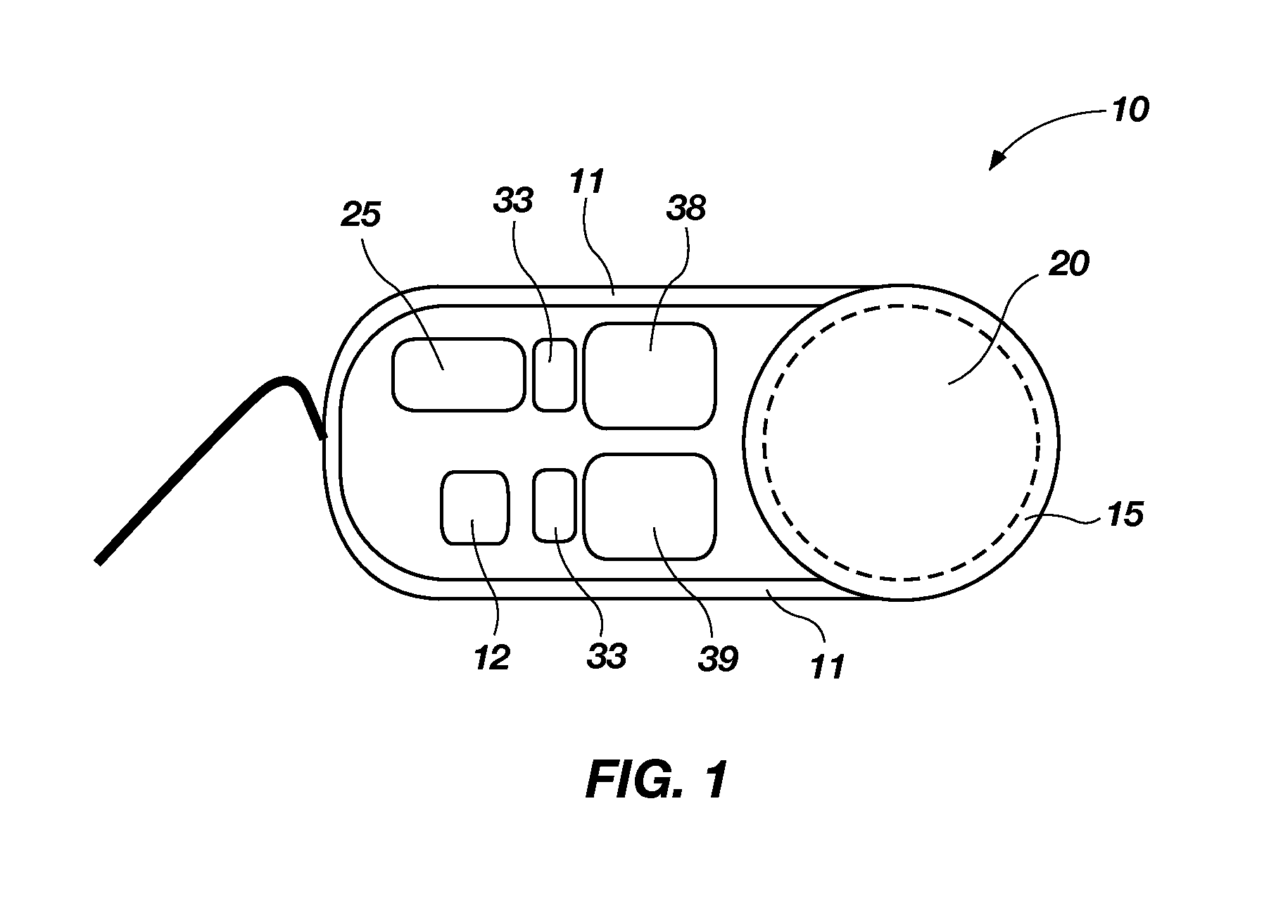
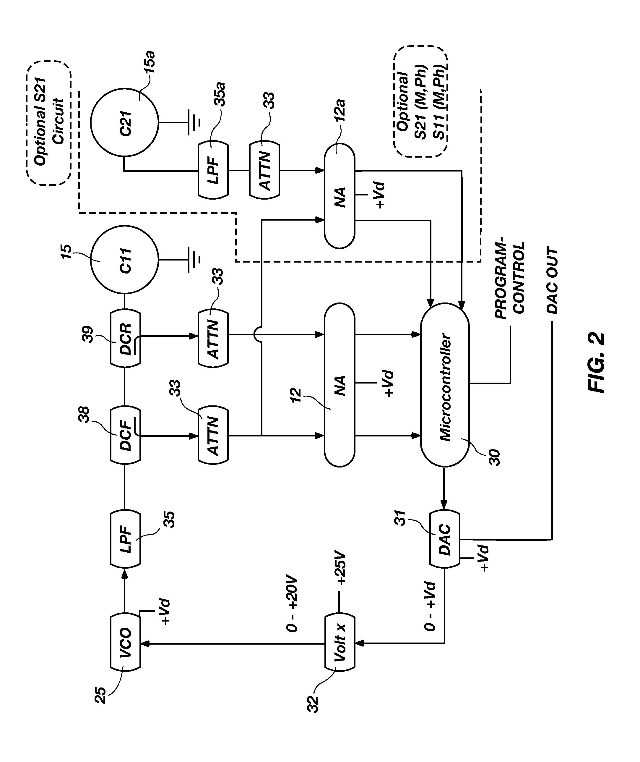
[0009]In accordance with additional embodiments, the present invention improves upon deficiencies in the prior art by providing a system for measuring the cardiac output of the heart of a patient, comprising a hand-held device comprising a housing containing a signal generator coupled to an antenna and a dielectric material disposed about the antenna, wherein said hand-held device is adapted to generate a plurality of radio frequency signals and direct said signals towards the heart of the person and measure a magnitude of a signal returned from the heart of the person. The hand-held device further comprises a processor contained within said housing, wherein said processor is adapted to compare

Problems solved by technology

Hemorrhage is a major cause of death of battlefield casualties who are not killed immediately and survive beyond the initial five minutes from injury.
Successful treatment requires immediate medical attention that can be very limited in the battlefield until the casualty is evacuated to higher echelons of care.
In healthy and physically trained individuals, these compensatory mechanisms maintain blood pressure disproportionately high within the body only to cause a rapid circulatory collapse as the hemorrhage causes massive loss of blood volume.
In addition to the delay in blood pressure drop caused by the compensatory mechanisms, arterial blood pressure is not available under battlefield conditions and is commonly substituted by traditional, non-invasive (occlusive) blood pressure measurements in peripheral circulation.
As mentioned above, the compensatory mechanisms that maintain blood supply to the vital organs do so by increasing peripheral resistance and diverting blood from the peripheral to central pool, causing the cessation of pressure pulse in peripheral circulation, and further difficulties in the determination of blood pressure.
None of the above methods has as yet fulfilled these requirements.

Method used


Image

  • Non-Invasive Method And Device For Measuring Cardiac Output
  • Non-Invasive Method And Device For Measuring Cardiac Output
  • Non-Invasive Method And Device For Measuring Cardiac Output

Examples


Embodiment Construction

)

[0024]The following detailed description of exemplary embodiments of the invention makes reference to the accompanying drawings, which form a part hereof and in which are shown, by way of illustration, exemplary embodiments in which the invention may be practiced. While these exemplary embodiments are described in sufficient detail to enable those skilled in the art to practice the invention, it should be understood that other embodiments may be realized and that various changes to the invention may be made without departing from the spirit and scope of the present invention. Thus, the following more detailed description of the embodiments of the present invention is not intended to limit the scope of the invention, as claimed, but is presented for purposes of illustration only to describe the features and characteristics of the present invention, and to sufficiently enable one skilled in the art to practice the invention. Accordingly, the scope of the present invention is to be de...


PUM


Abstract

A system comprising a housing containing a signal generator coupled to an antenna and a dielectric material disposed about the antenna. The device is adapted to generate and direct a plurality of signals towards the heart of the person and measure a magnitude of a signal returned from the heart. The device further comprises a processor to compare differences between a magnitude of a signal propagated and the magnitude of the signal returned off the heart and determine a signal frequency having a maximum return loss value based on those differences. The processor also estimates a change in the amplitude of motion of a portion of a wall of the heart based on the differences between the magnitude of the signal propagated by the device and the magnitude of the signal returned off of the portion of the heart.

Description

PRIORITY CLAIM[0001]This application claims the benefit of U.S. Provisional Application No. 61 / 010,035 filed on Jan. 4, 2008 entitled “Non-Invasive Method and Device for Measuring Cardiac Output” the entirety of which is incorporated herein by reference.GOVERNMENT[0002]This invention was made with government support under Grant No. DAMD1700C0013 awarded by the Department of Defense. The government has certain rights in the invention.FIELD OF THE INVENTION[0003]The present invention relates to medical devices, and more particularly to devices and methods of operation of said devices for non-invasively measuring the cardiac output of a patient.BACKGROUND[0004]There are numerous parameters that are measured invasively and non-invasively to gain diagnostic information about the cardiovascular system. The major function of the cardiovascular system is to supply sufficient amounts of oxygen and nutrients to meet the metabolic demands of the tissues. Cardiac output is a primary determinant...

Claims


Application Information

Patent Timeline
IPC IPC(8): A61B5/02
CPCA61B5/02028A61B5/0507A61B5/05A61B5/029
Inventor PETERSON, STEPHEN C.PETELENZ, TOMASZ J.JACOBSEN, STEPHEN C.
Owner SARCOS LC
Learn More