
Method of making bearing using ultrasonic NANO crystal surface modification technology

a technology of nano crystals and surface modifications, applied in the direction of manufacturing tools, superfinishing machines, mechanical equipment, etc., can solve the problems of difficult to evenly process the surface of bearings, and achieve the effects of improving fatigue life, and reducing the friction coefficient and wear rate of bearings

Active Publication Date: 2010-02-04
DESIGNMECHA
View PDF8 Cites 7 Cited by
  • Summary
  • Abstract
  • Description
  • Claims
  • Application Information

AI Technical Summary

Benefits of technology

[0015]One aspect of the present invention provides a bearing processing system using an ultrasonic nano crystal surface modifier and a processing method using the same by which a hammering speed, a hammering progress speed, a hammering angle, etc. of the ultrasonic nano crystal surface modifier are precisely controlled to control sizes and directions of micro-dimples and a contact count of dimples per unit area so as to reduce a friction coefficient and a wear rate of a bearing during sliding or rolling and improve a fatigue life occurring when the bearing is bent, twisted, sealed, or compressed.
[0016]A bearing processing system using an ultrasonic nano crystal surface modifier according to an aspect of the present invention may precisely control a hammering speed, a hammering progress speed, a hammering angle, etc. of the ultrasonic nano crystal surface modifier. Thus, the bearing processing system may freely control sizes and directions of micro-dimples, a contact count of micro-dimples per unit area, etc. so as to reduce a friction coefficient and a wear rate of a bearing during sliding or rolling of the bearing. Also, the bearing processing system may apply compressive residual stress to a surface of the bearing and improve surface hardness of the bearing to improve rolling contact fatigue strength. In addition, the bearing processing system may improve a fatigue life occurring when the bearing is bent, twisted, sealed, or compressed.

Problems solved by technology

However, in such a surface hardening processing method, it is difficult to evenly process a surface of a bearing.
Further in the foregoing method, the bearing intermediate prior to repeatedly impacting may comprise a substantial amount of micro-hair cracks at or underneath the surface.

Method used


Image

  • Method of making bearing using ultrasonic NANO crystal surface modification technology
  • Method of making bearing using ultrasonic NANO crystal surface modification technology
  • Method of making bearing using ultrasonic NANO crystal surface modification technology

Examples


Embodiment Construction

[0037]Embodiments will now be described more fully with reference to the accompanying drawings, in which embodiments of the invention are shown. The invention may, however, be embodied in many different forms and should not be construed as being limited to the embodiments set forth herein; rather, these embodiments are provided so that this disclosure will be thorough and complete, and will fully convey the concept of the invention to those skilled in the art.

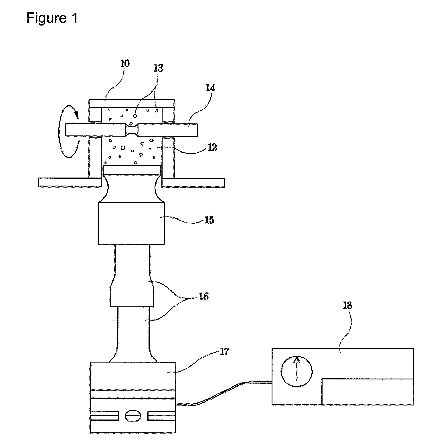
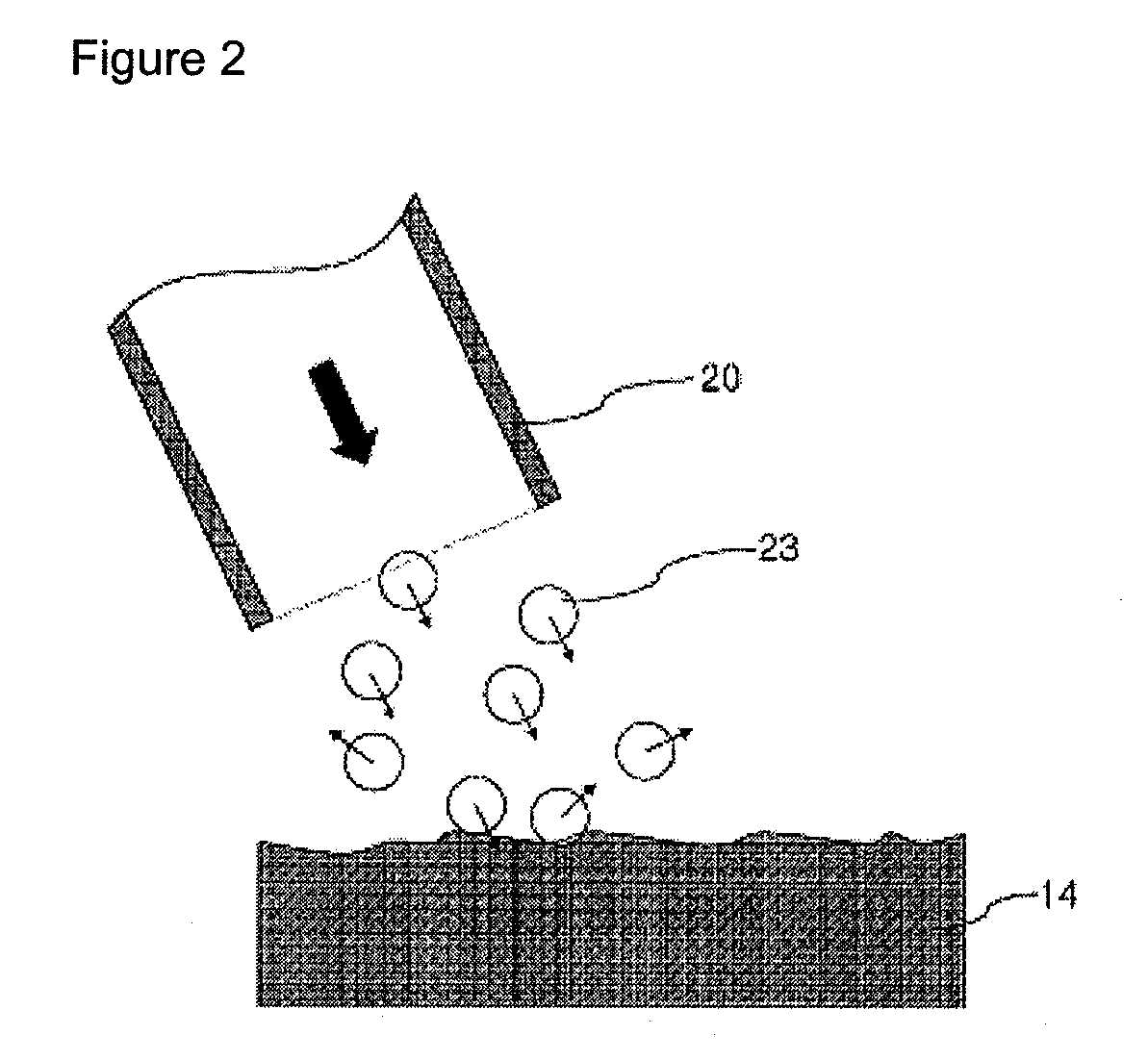
[0038]FIG. 1 illustrates a surface modifying method using ultrasonic waves, and FIG. 2 illustrates a surface modifying method using shot peening. In theses surface modifying methods of FIG. 1 or 2, a plurality of abrasive particles 13 or shot balls 23 clash onto a material 14 to be processed. Next, relatively protruding portions of the material 14 are locally plastically deformed so as to obtain smooth surface roughness of the material 14.

[0039]These surface modifying methods will now be described in more detailed. In the surfa...


PUM

PropertyMeasurementUnit
roughnessaaaaaaaaaa
angleaaaaaaaaaa
speedaaaaaaaaaa

Abstract

A method of making a bearing includes providing a bearing intermediate, which is unfinished while having an overall shape of a finished bearing product; and repeatedly impacting a surface of the bearing intermediate at one or more ultrasonic frequencies to modify characteristics of the bearing intermediate. The resulting bearing intermediate or finished bearing product includes nano-size grains at or underneath the surface.

Description

RELATED APPLICATIONS[0001]This application is a continuation in part application under 35 U.S.C. §365(c) of International Application No. PCT / KR2008 / 003006, filed May 29, 2008 designating the United States. This application further claims the benefit of the earlier filing date under 35 U.S.C. §365(b) of Korean Patent Application No. 10-2008-0044506 filed May 14, 2008. This application incorporates herein by reference the International Application No. PCT / KR2008 / 003006 and the Korean Patent Application No. 10-2008-0044506 in their entirety.BACKGROUND[0002]1. Field[0003]The present disclosure relates to a process of making a bearing using an ultrasonic nano crystal surface modification technology.[0004]2. Discussion of the Related Art[0005]A bearing refers to a mechanical element which fixes a shaft of a machine, which is rotating, in a predetermined position and rotates the shaft in support of a weight of the shaft and load imposed on the shaft. Since the bearing is rubbed, bent, twi...

Claims


Application Information

Patent Timeline
Patent Type & Authority Applications(United States)
IPC IPC(8): B21D53/10
CPCY10T29/49709Y10T29/49707B24B35/00F16C33/64B24B39/006B24B1/04B82Y99/00
Inventor PYUN, YOUNG SIKPARK, JEONG HYEONKIM, CHANG SIKCHO, IN HO
Owner DESIGNMECHA
Learn More