Structural element and methods of use thereof

a structural element and structural technology, applied in the field of structural elements and structural components, can solve the problems of poor underside surface finish, large cost of existing construction systems using pre-cast elements, and large cost of pre-cast elements

Inactive Publication Date: 2010-02-04
VALAIRE TREVOR
View PDF26 Cites 15 Cited by
  • Summary
  • Abstract
  • Description
  • Claims
  • Application Information

AI Technical Summary

Benefits of technology

[0008]The present invention seeks to provide an improved plank for use in forming concrete flooring which addresses and at least partially alleviates some of the problems of the prior art assemblies as discussed above.

Problems solved by technology

Cast in situ reinforced concrete floors, require extensive formwork, are relatively time consuming and labour intensive particularly with respect to the assembly and dismantling of formwork and the time required for the in situ concrete to achieve the required strength.
Existing construction systems using pre-cast elements have significant cost and other disadvantages including poor underside surface finish, ribbed profiles on the underside necessitating separate ceilings in many applications, difficulty of running services through and lack of flexibility of the type of structures which can be built.
These disadvantages render in situ casting construction the preferred method of slab and floor construction.
This construction system can span relatively long distances, but has the disadvantage that it typically has a very poor surface finish on the underside necessitating in many applications a false ceiling or cladding over the concrete finish.
The structural planks are typically produced in quite narrow strips requiring many joints and it is difficult to put services through the floor, as it is very difficult to access the voids.
Also the planks are relatively thick and the services typically have to be either hung on the underside, also necessitating false ceilings in some applications or the services may be hidden in thick topping concrete.
A further disadvantage of Ultrafloor is that it has a limited span both during concrete pouring and as a finished floor.
Ultrafloor is limited in the types of floor structure which can be made from the basic panel and from the panel used in conjunction with the shell beam.
This system has the disadvantage that it is limited to relatively short spans of about 7 m or so.

Method used


Image

  • Structural element and methods of use thereof
  • Structural element and methods of use thereof
  • Structural element and methods of use thereof

Examples


Embodiment Construction

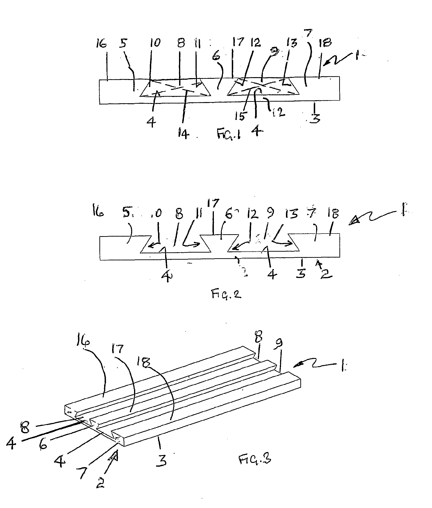
[0068]FIG. 1 shows an end view of a pre-cast concrete element 1 comprising a base 2 having an underside surface 3 and upper surface 4. Element 1 further comprises formations 5, 6 and 7 which define void spaces 8 and 9. Void 8 is defined by upper surface 4 and side walls 10 and 11. Void 9 is defined by upper surface 4 and side walls 12 and 13. In the embodiment of FIG. 1 voids 8 and 9 are filled with polystyrene or similar lightweight material which maintains a lighter weight than an equivalent element with voids filled with concrete or cement. Element 1 typically includes reinforcing (not shown) in base 2, typically reinforced with steel bars or prestressed reinforcement above which two or more polystyrene void formers 14 and 15 preferably in the shape of an isosceles trapezium are located.

[0069]Formations 5, 6 and 7 comprise ribs with longitudinal extent and whose width increases as the distance from surface 4 increases so that there is more material at the top of the formations 5,...


PUM


Abstract

A pre-formed structural concrete element for use in the formation of a composite concrete floor of a building or the like, the element comprising: a generally planar base portion having opposing faces; a series of generally parallel spaced apart formations extending from one said faces of the base portion each defining along with an adjacent formation a void space therebetween and wherein the formations terminate in a plateau and have at least a narrow portion and a wide portion between the plateau and the one said faces of the base portion.

Description

BACKGROUND[0001]The present invention relates to structural engineering and more specifically to a structural member capable of use in the construction of structures such as concrete slabs and elements. The invention further relates to methods of use of the structural member including its application in preparatory formwork and as an element in a composite structure including in layered concrete. The invention also relates to structures which employ the structural member. The invention further relates to lightweight structural members used in a variety of concrete structures.PRIOR ART[0002]Slab beam concrete constructions is widely used in civil and structural engineering. The typical structure will comprise columns of a size dictated by applied such as dead loads and self weight and live loads and of a spacing dictated by loadings and slab spans. Reinforced and pre stressed concrete floors for buildings are generally made in one of two methods. The floors are either cast in situ us...

Claims


Application Information

Patent Timeline
Patent Type & Authority Applications(United States)
IPC IPC(8): E04B5/04E04B1/16
CPCE04B5/43E04B5/38E04B5/16E04B5/17E04C3/20
Inventor VALAIRE, TREVOR
Owner VALAIRE TREVOR
Why Eureka
Try Eureka