

Displacement measuring instrument and displacement measuring method
- Summary
- Abstract
- Description
- Claims
- Application Information
AI Technical Summary
Benefits of technology
Problems solved by technology
Method used
Image

Examples
Embodiment Construction
)
[0055]A laser interferometric measuring instrument will be exemplarily described as a displacement measuring instrument according to an exemplary embodiment of the invention with reference to the attached drawings.
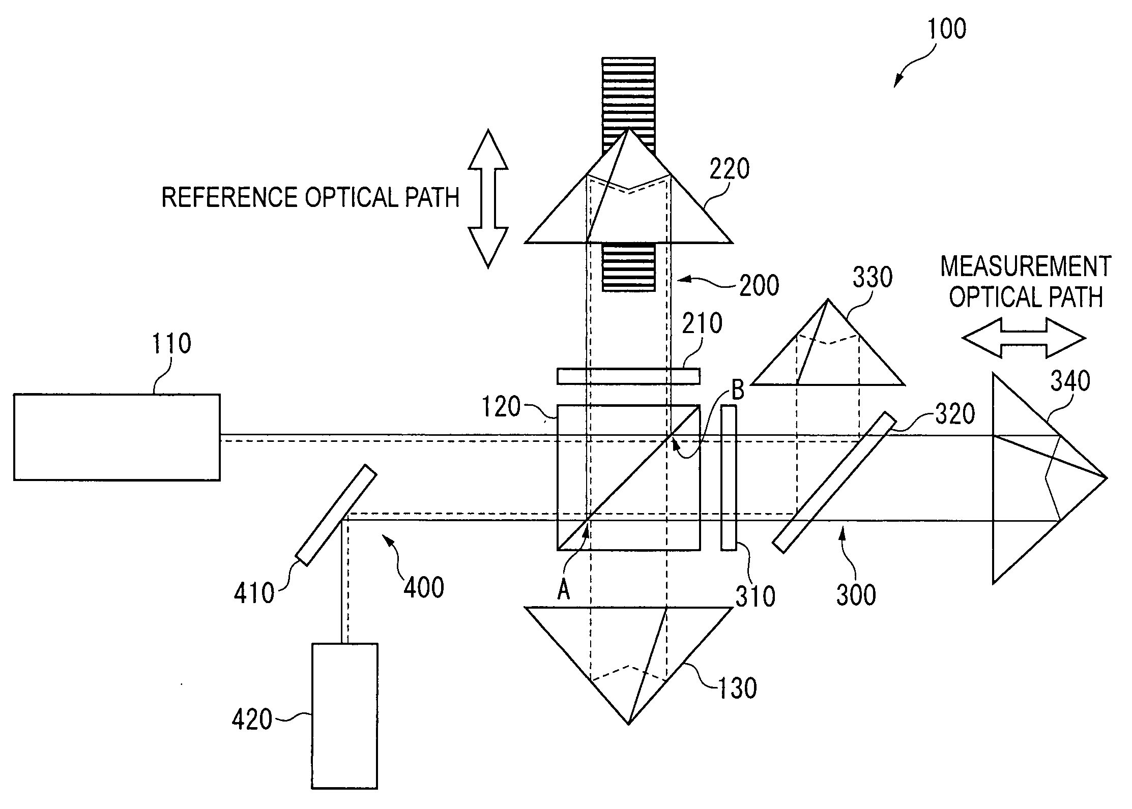
[0056]FIG. 4 is a block diagram schematically showing a laser interferometric measuring instrument according to the exemplary embodiment of the invention.
[0057]A laser interferometric measuring instrument 1 measures, for example, a displacement D of a target object 3 on a stage 2 as shown in FIG. 4. The laser interferometric measuring instrument 1 is incorporated in a machine tool for producing precision components, a highly accurate measuring instrument, a microscopic profile measuring instrument or the like to accurately measure a displacement of a target object in 10−12 m. In this exemplary embodiment, the laser interferometric measuring instrument 1 for measuring the displacement of the target object 3 provided on the stage 2 is exemplarily explained. However, the las...
PUM
 Abstract
Description
Claims
Application Information