Supercharge Your Innovation With Domain-Expert AI Agents!

Optical communication device, optical communication system, optical output control method and program

a technology of optical communication device and control method, which is applied in the direction of multiplex communication, transmission monitoring, fault recovery arrangements, etc., can solve the problems of connector end surface catching fire, damage occurring, and it is not possible to visually confirm optical communication devices

Active Publication Date: 2010-02-04
NEC CORP
View PDF40 Cites 6 Cited by
  • Summary
  • Abstract
  • Description
  • Claims
  • Application Information

AI Technical Summary

Benefits of technology

[0015]In the optical communication device, the receiving unit may receive an optical output restart command from the other optical communication device, and the command executing unit, when the optical output restart command is input, may raise the output level of optical signals from the transmitting unit to the output level used during normal operations.
[0024]In still another embodiment, there is provided a program which causes a computer of an optical communication device which transmits and receives optical signals via an optical fiber cable to function: as a transmitting unit which transmits optical signals to another optical communication device; as a receiving unit which receives an optical output stop command or an optical output reduction command from the other optical communication device; and as a command executing unit which, when the optical output stop command is input, executes processing to stop the output of optical signals from the transmitting unit, or when the optical output reduction command is input, executes processing to reduce the output level of optical signals from the transmitting unit to less than the output level used during normal operations.
[0025]Still more, the program may further cause the computer to function: as a receiving unit which receives an optical output restart command via the optical fiber cable; and as a command executing unit which, when the optical output restart command is input, raises the output level of optical signals from the transmitting unit to the output level used during normal operations.

Problems solved by technology

The optical output level from an optical communication device is extremely high, and if an optical fiber connection is cut without this optical output being stopped or decreased, there is a possibility of damage occurring such as a connector end surface catching fire because of contamination or the like, or such as the maintenance operator suffering harmful physical effects.
However, because the respective optical communication devices are normally installed at remote distances, it is not possible to visually confirm those optical communication devices which are connected to the maintenance segment.
At this time, there is a possibility that optical communication devices which should not be shut down will be shut down due to the network connection diagram being misinterpreted or to an incorrect operation or the like.
If an optical communication device which should not be shut down is shut down, then because communication is also stopped outside the maintenance segment, this creates considerable impediments to the providing of a service.
Furthermore, because the optical output is not stopped in the maintenance segment, the problem arises that it is not possible to guarantee the safety of maintenance operators.
Moreover, because the methods described in Japanese Unexamined Patent Application, First Publications, Nos. 2000-332695 and 2004-297790 are both methods in which a fault is detected and then an APR function is put into operation, other than when a fault occurs it has not hitherto been possible to either stop or reduce the optical output in order to perform a maintenance operation such as, for example, when connections need to be altered in an optical fiber cable because of modifications to the transmission route.

Method used


Image

  • Optical communication device, optical communication system, optical output control method and program
  • Optical communication device, optical communication system, optical output control method and program
  • Optical communication device, optical communication system, optical output control method and program

Examples


first embodiment

[0036]A first embodiment of the present invention will now be described in detail with reference made to the drawings.

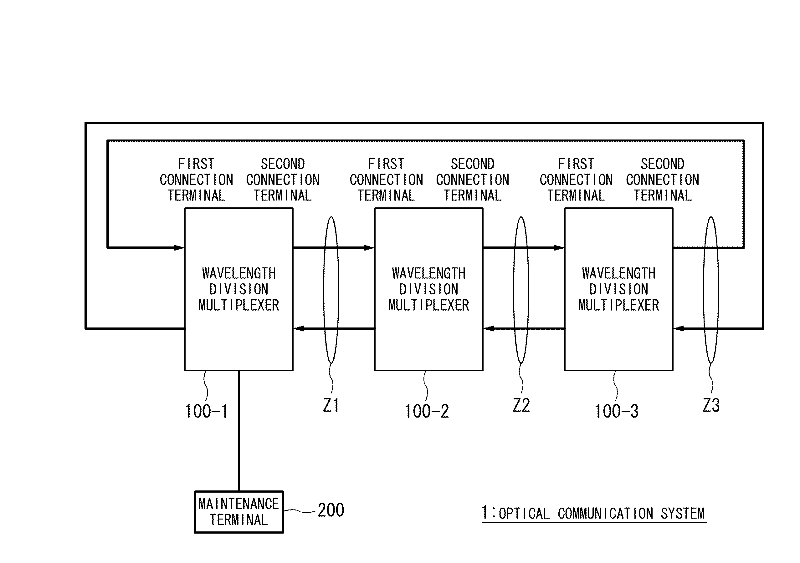
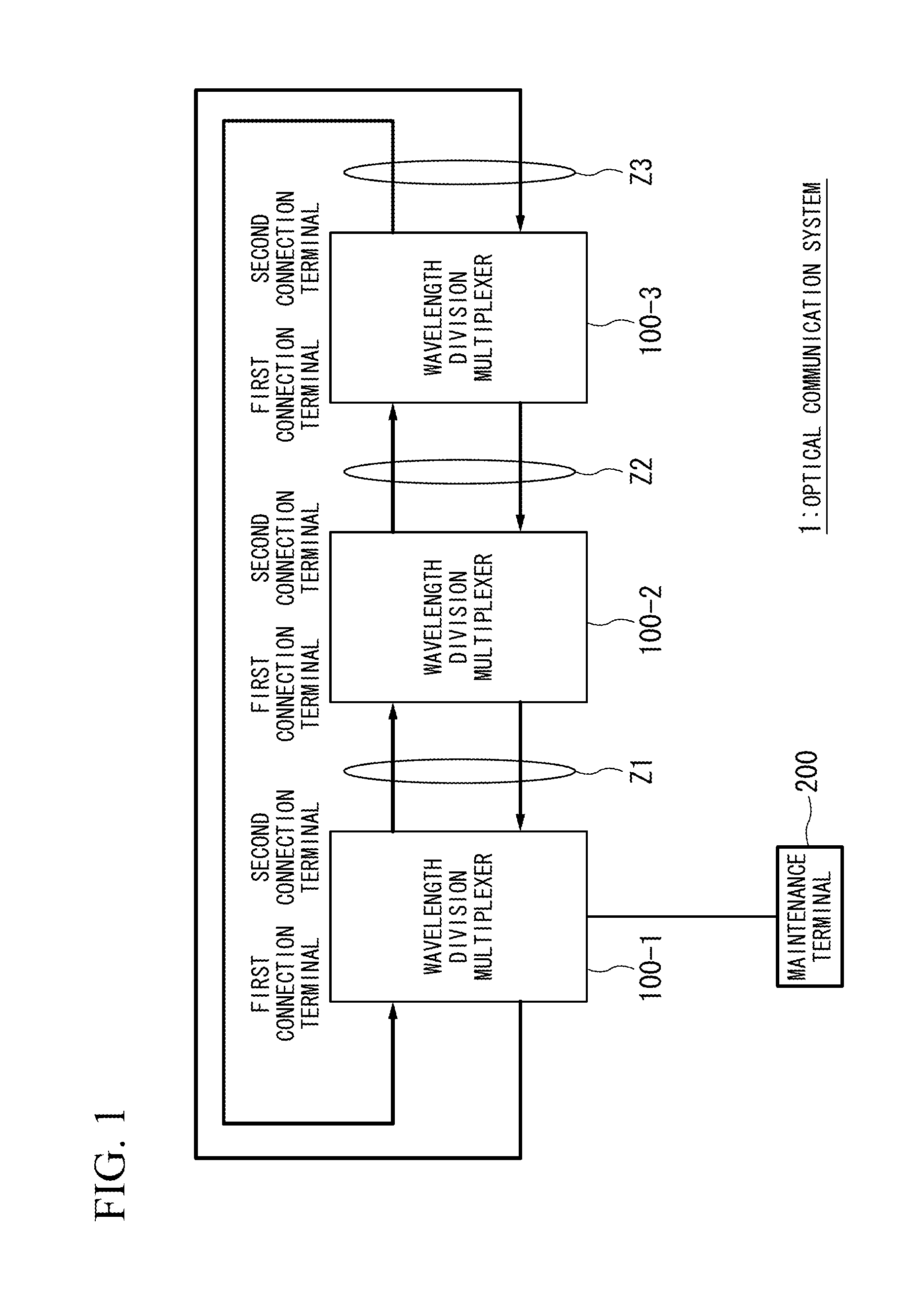
[0037]FIG. 1 is a schematic block diagram showing the structure of an optical communication system according to the first embodiment of the present invention.

[0038]The optical communication system shown in FIG. 1 shows an example in which three wavelength division multiplexers (i.e., optical communication devices) are connected in sequence so as to construct a ring-shaped optical communication system whose nodes are formed by these wavelength division multiplexers. An optical communication system 1 is provided with wavelength division multiplexers 100-1 through 100-3 and with a maintenance terminal 200. The wavelength division multiplexers 100-1 through 100-3 each have a first connection terminal and a second connection terminal. The second connection terminal of the wavelength division multiplexer 100-1 is connected to the first connection terminal of the wavelength...

second embodiment

[0060]Next, a second embodiment of the present invention will be described. In the second embodiment, an example is given of optical output control in an optical communication system which employs a Raman amplification excitation light source.

[0061]FIG. 5 is a schematic block diagram showing the structure of an optical communication system according to the second embodiment of the present invention.

[0062]The wavelength division multiplexers 100-1 through 100-3 of the optical communication system 1 according to the second embodiment are each provided with Raman light sources which are connected to an optical fiber cable on the receiving side of each wavelength division multiplexer, and output excitation light in the opposite direction from received signals. Excluding the fact that they are provided with Raman light sources, because the rest of the structure is the same as in the optical communication system of the first embodiment, the same symbols are used in the description.

[0063]F...


PUM


Abstract

An input of a command to stop optical output or a command to reduce optical output by a main signal transmitting section is received from the outside. When the input of the optical output stop command or optical output reduction command is received, an inter-device control signal communication section transmits the optical output stop command or optical output reduction command. Based on the input optical output stop command or optical output reduction command, an output of optical signals from the main signal transmitting section is stopped, or else the output level is reduced to less than the output level during normal operation.

Description

[0001]This application is based upon and claims priority to Japanese Patent Application No. 2008-199625, filed Aug. 1, 2008, the content of which is incorporated herein in its entirety by reference.BACKGROUND OF THE INVENTION[0002]1. Field of the Invention[0003]The present invention relates to an optical communication device which uses high output light such as wavelength division multiplexers and optical cross-connect devices, and to an optical output control method, an optical communication system, and a program thereof.[0004]2. Description of Related Art[0005]When maintenance is being carried out on an optical communication system, connections between optical fiber cables and optical communication devices such as wavelength division multiplexers are cut. The optical output level from an optical communication device is extremely high, and if an optical fiber connection is cut without this optical output being stopped or decreased, there is a possibility of damage occurring such as...

Claims


Application Information

Patent Timeline
IPC IPC(8): H04J14/02H04B10/07H04B10/03H04B10/079H04B10/275
CPCH04B10/07955H04B2210/08H04J14/0227H04J14/0283H04J14/0267H04J14/0246H04J14/025H04J14/0254H04J14/0284H04J14/0221H04J14/0272
Inventor NISHINO, MASARU
Owner NEC CORP
Features
  • R&D
  • Intellectual Property
  • Life Sciences
  • Materials
  • Tech Scout
  • Unparalleled Data Quality
  • Higher Quality Content
  • 60% Fewer Hallucinations
Learn More