Oil-flooded screw compressor, motor drive system, and motor control device

a screw compressor and oil-flooded technology, applied in the direction of motor/generator/converter stopper, dynamo-electric converter control, instruments, etc., can solve the problems of compressor halt in such a state, large oil accumulation inside, etc., to reduce weight and manufacturing costs, smooth start-up of oil-flooded screw compressors, the effect of smooth start-up

Active Publication Date: 2010-02-04
HITACHI IND EQUIP SYST CO LTD
View PDF3 Cites 20 Cited by
  • Summary
  • Abstract
  • Description
  • Claims
  • Application Information

AI Technical Summary

Benefits of technology

[0021]In accordance with the present invention, smooth start-up of oil-flooded screw compressors can be ensured. In addition, because such smooth start-up can be ensured by a structure comprising small, low-output dev

Problems solved by technology

Thus, much oil accumulates inside the working chamber

Method used


Image

  • Oil-flooded screw compressor, motor drive system, and motor control device
  • Oil-flooded screw compressor, motor drive system, and motor control device
  • Oil-flooded screw compressor, motor drive system, and motor control device

Examples


second embodiment

[0031]Further, when an oil-flooded screw compressor according to the invention receives a halt instruction during operation, the compressor operates to halt its electric motor and at the same time discharges high-pressure gas that remains inside the pipe that communicates with the discharge side of its rotor casing. Thus, the high pressure on the discharge side decreases gradually to as low as the intake-side pressure. Thereafter, the rotors are controlled so as to rotate at a low rotational speed for only a short amount of time.

third embodiment

[0032]Furthermore, an oil-flooded screw compressor according to the invention includes a pathway that communicates with a lower section of an internal intake-side space of the casing and with an oil reservoir which is located below the lower section of the casing that houses rotors and also includes a check valve in the middle of the pathway, the check valve allowing oil to flow only in the direction from the internal intake-side space of the casing to the oil reservoir.

first embodiment

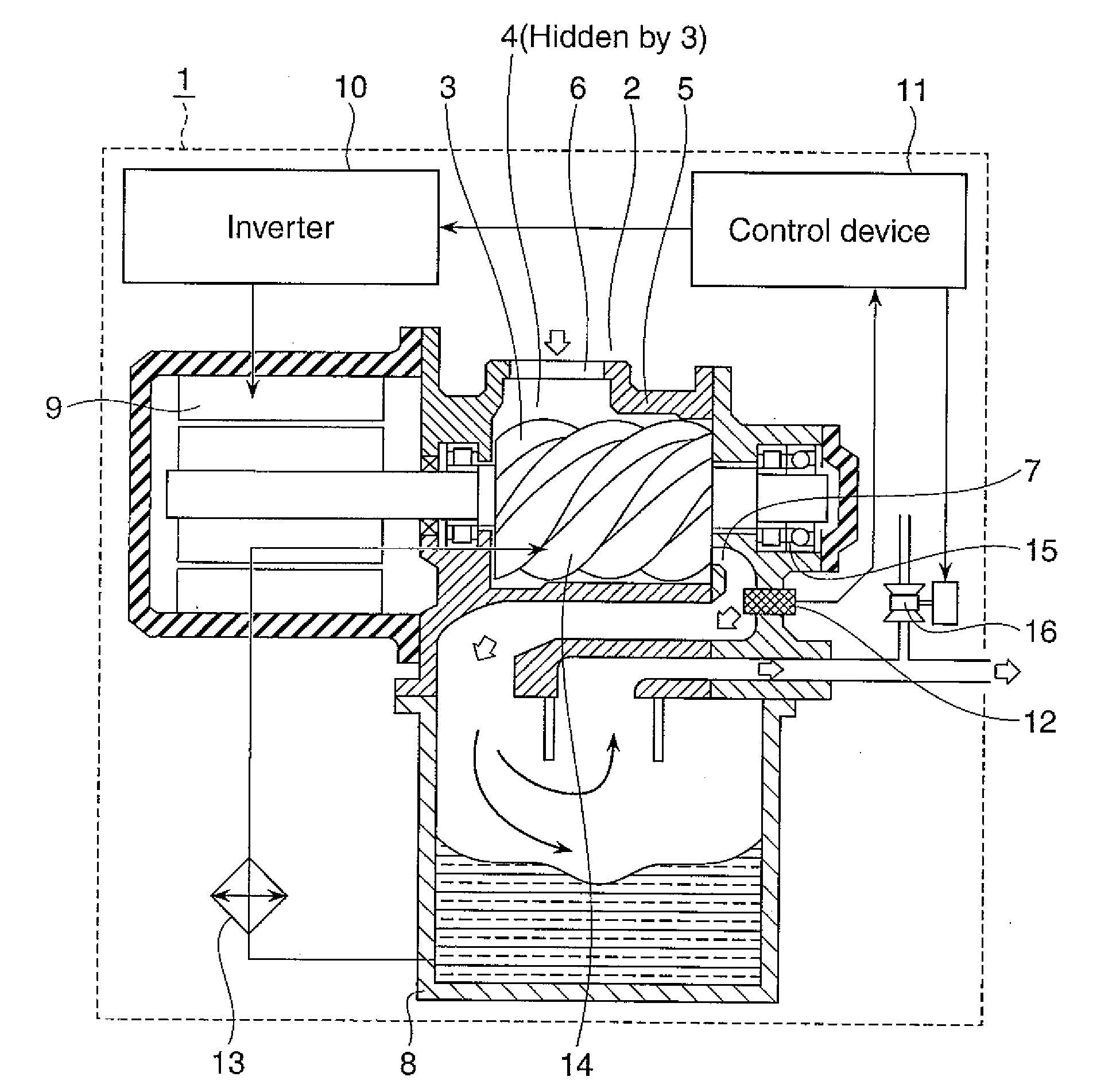
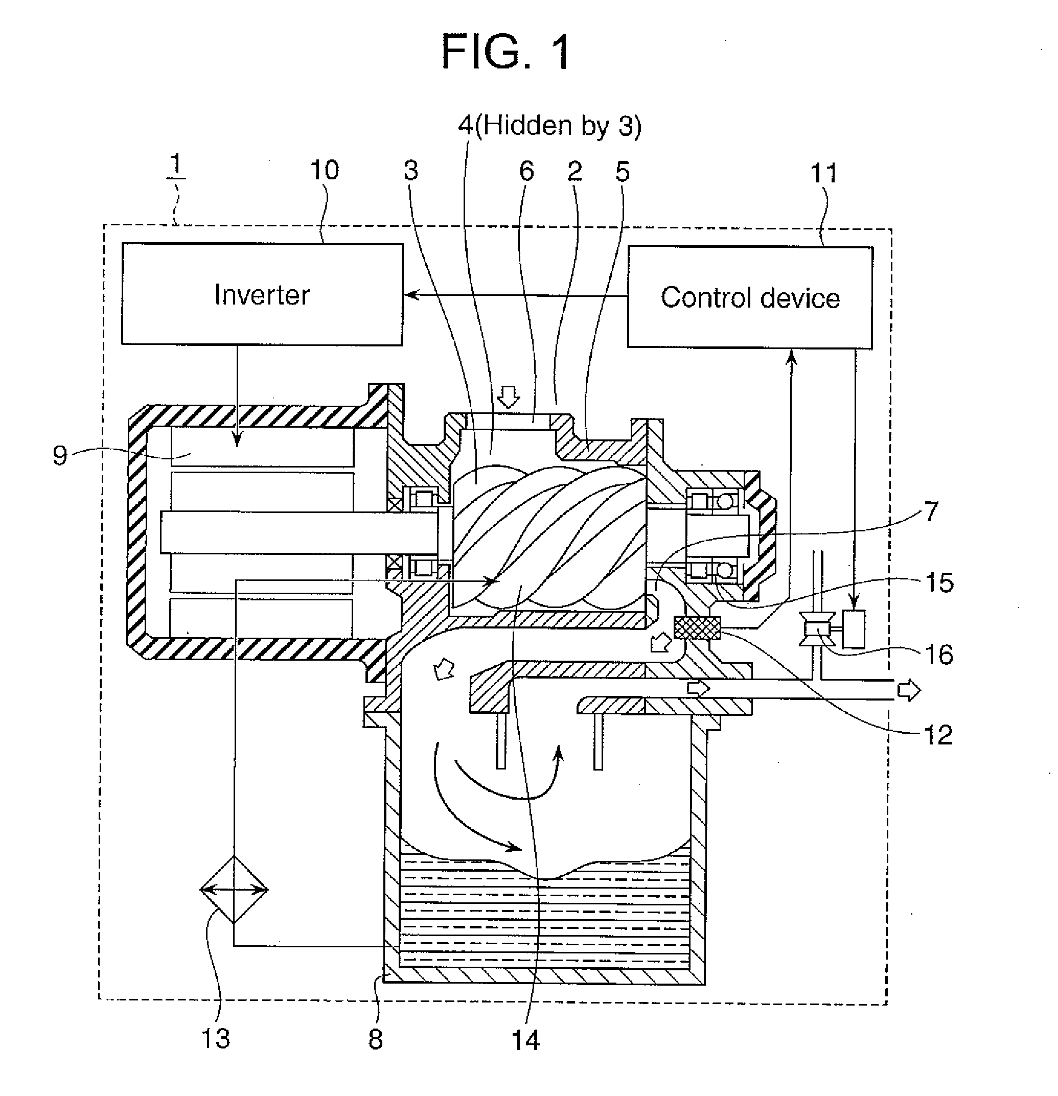
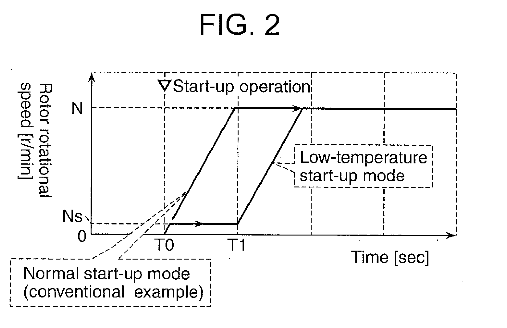
[0033]The preferred embodiments of the invention are discussed in detail below. the invention is described first with reference to FIGS. 1 and 2. FIG. 1 is a schematic illustrating an oil-flooded screw air compressor (hereinafter also referred to as “air compressor”), and FIG. 2 is a graph showing changes in the rotational speed of its rotors before and after start-up.

[0034]The air compressor, designated 1, houses a compressor body 2 in which meshed male and female rotors, 3 and 4, respectively, are provided rotatably. The rotors 3 and 4 have screw-thread-shaped groove on the outer surfaces of their respective rotary shafts.

[0035]The casing 5 that houses the rotors 3 and 4 has internal spaces that surround the outer-circumferential areas of the rotors 3 and 4 and the end faces of the rotors 3 and 4 in a shaft-extending direction. The casing 5 is provided with a suction port 6 through which air is drawn in for compression and a delivery port 7 through which compressed air is discharg...


PUM


Abstract

When an oil-flooded screw compressor is started up in a cold environment after a long halt, start-up torque increases due to the increased viscosity of the oil that has long stayed inside the working chambers of the compressor. This has necessitated drive means with a larger capacity than that required for normal operation.
An oil-flooded screw compressor according to the invention comprises: a casing; a pair of rotors each having screw-thread-shaped groove and being housed in the casing; an electric motor for rotationally driving the pair of rotors; a control device for controlling the electric motor; an oil feeding mechanism for feeding oil into working chambers formed by being enclosed by the casing and the pair of rotors in which teeth thereof are meshed to each other; and an oil separating mechanism for separating the oil from compressed gas discharged from the working chambers. The oil-flooded screw compressor drives the pair of rotors at a rotational speed which is low enough not to increase torque for a short amount of time after start-up and accelerates the pair of rotors up to a normal-operation rotational speed after oil discharge. Alternatively, the oil-flooded screw compressor rotates the pair of rotors for a short amount of time after the remaining compressed gas is discharged after a halt, thereby allowing the oil accumulated inside the working chambers to be discharged and ensuring smooth start-up after the halt.

Description

BACKGROUND OF THE INVENTION[0001]1. Field of the Invention[0002]The present invention relates generally to oil-flooded screw compressors and also to technologies for avoiding increase in loads on electric motors and power supply circuitry used to drive the compressors.[0003]2. Description of the Related Art[0004]An oil-flooded screw compressor includes therein multiple enclosed spaces, called working chambers or compression cavities, which are formed by meshing the groove of two counter rotors and reducing the spaces between the rotors and the casing that houses the rotors.[0005]While the two meshed counter rotors rotate, each working chamber moves inside the casing, alternating expansion and shrinkage in its volume. Depending on a position of rotors inside the casing, each working chamber communicates with the outside via an opening of the casing or is in an enclosed state. During volume expansion, a working chamber continues to communicate with an opening called a suction port, al...

Claims


Application Information

Patent Timeline
IPC IPC(8): F04B49/00F04B35/04F04C29/04H02P1/04F04C18/16F04C28/06
CPCF04C18/16F04C28/06F04C28/08F04B17/03F04C2270/19F04C2270/701F04C2270/051
Inventor KAMEYA, HIROTAKAYAMASAKI, MASARUAJIMA, TOSHIYUKISENOO, MASAHARUTANAKA, HIDEHARUSUZUKI, NORINAGA
Owner HITACHI IND EQUIP SYST CO LTD
Why Eureka
Try Eureka