Inverter-integrated electric compressor

Inactive Publication Date: 2010-02-04
MITSUBISHI HEAVY IND LTD
View PDF1 Cites 2 Cited by
  • Summary
  • Abstract
  • Description
  • Claims
  • Application Information

AI Technical Summary

Benefits of technology

[0025]Accordingly, since at least one of the capacitor, the inductor, and the common mode coil is disposed upstream in the flow direction of a refrigerant gas drawn through the refrigerant suction port with respect to the power board. Therefore, the capacitor, the inductor, and the common mode coil, which are high-voltage components that have a relatively low temperature, can be cooled first. In this way, a temperature rise in the refrigerant can be suppressed as much as possible, and the power board (board on which power devices, such as IGBTs, are mounted) disposed downstream can be efficiently cooled. Therefore, the cooling effect on all high-voltage components constituting the inverter dev

Problems solved by technology

Therefore, as described in Patent Document 2, it is difficult to employ a configuration in which the inverter device is provided separately.
Furthermore, as described in Patent Document 1, even when the inverter is integrated, the cooli

Method used


Image

  • Inverter-integrated electric compressor
  • Inverter-integrated electric compressor
  • Inverter-integrated electric compressor

Examples


first embodiment

[0047

[0048]A first embodiment of the present invention will be described below with reference to FIGS. 1 to 4.

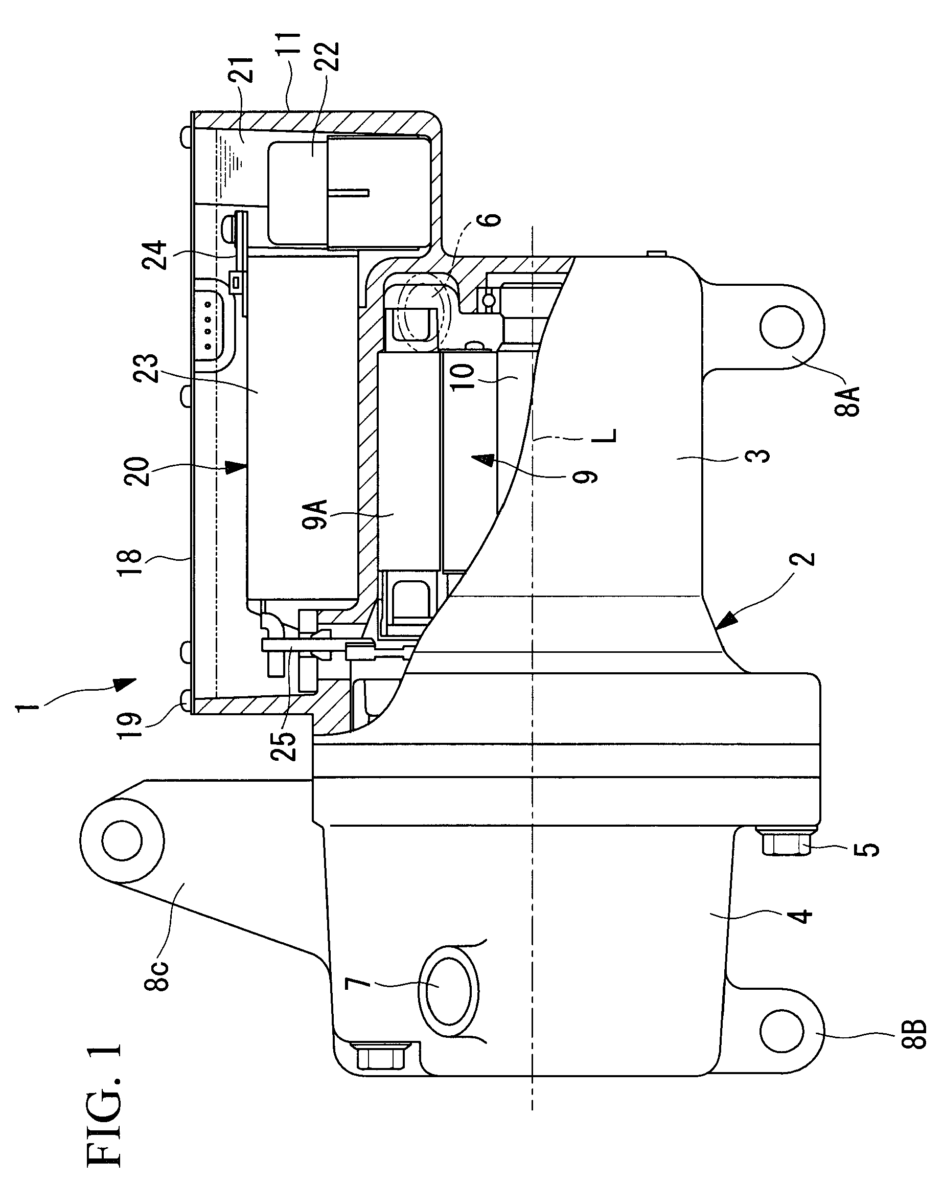
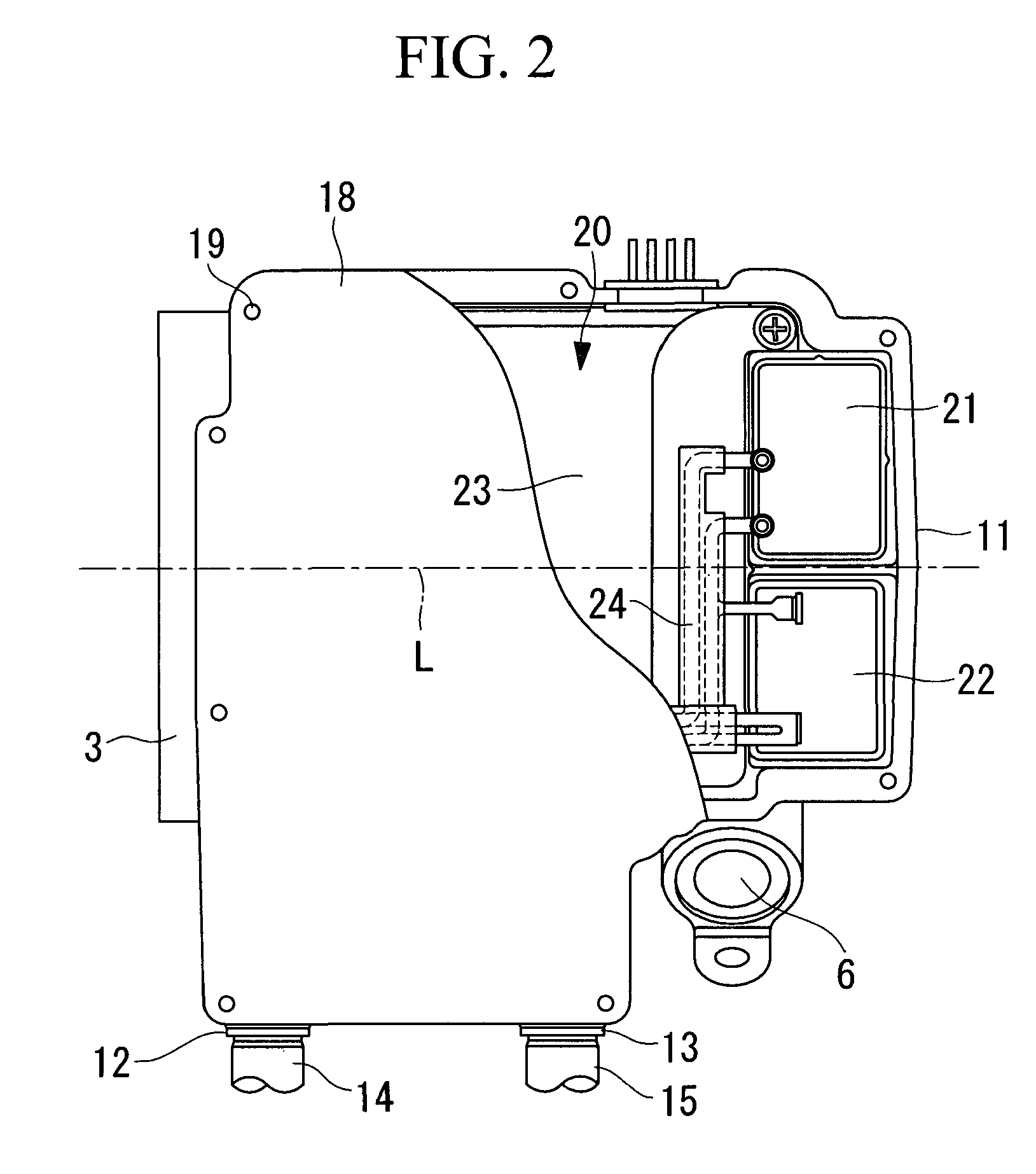
[0049]FIG. 1 illustrates a partial longitudinal sectional view of an inverter box section of an inverter-integrated electric compressor according to the first embodiment of the present invention. FIG. 2 is a plan view illustrating part of FIG. 1. An inverter-integrated electric compressor 1 includes a housing 2 that forms the outer shell thereof. The housing 2 is constructed by integrating a motor housing 3 for accommodating an electric motor 9 and a compressor housing 4 for accommodating a compressing mechanism, which is not shown in the drawing, by tightening bolts 5. The motor housing 3 and the compressor housing 4 are formed by aluminum die-casting.

[0050]The electric motor 9 and the compressing mechanism, which is not shown in the drawing, accommodated inside the housing 2 are linked via a motor shaft 10 (see FIG. 1), and the compressing mechanism is driven by rotation o...

second embodiment

[0065

[0066]Next, a second embodiment of the present invention will be described with reference to FIG. 5.

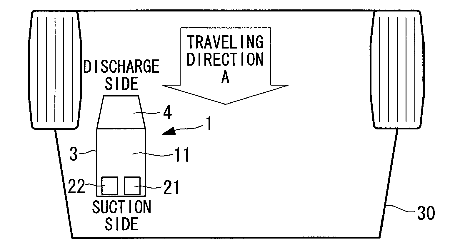
[0067]This embodiment differs from the above-described first embodiment in that the mounting orientation of the inverter-integrated electric compressor 1 in the vehicle 30 is different and thus the positioning of the high-voltage components is different. Other aspects are the same as those in the first embodiment, and thus, descriptions thereof are omitted.

[0068]In this embodiment, as shown in FIG. 5, the inverter-integrated electric compressor 1 is mounted on the vehicle 30 in the left-to-right direction such that the motor shaft direction L (the Z axis direction of the X, Y, and Z axes of the inverter-integrated electric compressor 1 shown in FIG. 3) is orthogonal to the traveling direction A of the vehicle 30, which is indicated by an arrow.

[0069]In such a case, the inverter-integrated electric compressor 1 is mounted in an orientation such that the side section (lower surface...


PUM


Abstract

It is an object to provide an inverter-integrated electric compressor capable of enhancing the cooling of high-voltage components, which generate a large amount of heat, among components of an inverter device disposed inside an inverter box integrated with a housing. An inverter-integrated electric compressor (1) for a vehicle air conditioner includes an inverter box (11) that is integrated with the periphery of a housing (2) accommodating an electric motor (9) and a compressing mechanism, an inverter device (20) that converts DC power to three-phase AC power and supplies it to the electric motor (9) being accommodated in the interior thereof, wherein, when the electric compressor is installed in a vehicle (30), among components of the inverter device (20), high-voltage components (21, 22) generate a large amount of heat are disposed inside the inverter box (11) at positions facing forward in a vehicle traveling direction.

Description

TECHNICAL FIELD[0001]The present invention relates to an inverter-integrated electric compressor that is integrated with an inverter device suitable for use as an air conditioning compressor installed in a vehicle.BACKGROUND ART[0002]An inverter-integrated electric compressor is constructed of an inverter box integrated with the periphery of a housing, which accommodates an electric motor and a compressing mechanism, the inverter box accommodating an inverter device that converts DC power received from a power supply, such as a generator or a battery, into three-phase AC power and feeds it to the electric motor. The inverter device includes high-voltage components, such a capacitor, an inductor, a common mode coil, and a power board (a board on which power devices, such as insulated gate bipolar transistors (IGBTs), are mounted), as components thereof. Not only do these high-voltage components generate a large amount of heat, but they are also heated by radiation heat caused by the ...

Claims


Application Information

Patent Timeline
IPC IPC(8): F04B39/06F04B17/03B60H1/32
CPCF04B39/066
Inventor ICHISE, YUKIWATANABE, TAKAYUKIHIRANO, TAKESHIHAGITA, TAKAYUKI
Owner MITSUBISHI HEAVY IND LTD
Why Eureka
Try Eureka