Rotary pump with coaxial magnetic coupling

Inactive Publication Date: 2010-02-04
H WERNERT & CO
View PDF5 Cites 35 Cited by
  • Summary
  • Abstract
  • Description
  • Claims
  • Application Information

AI Technical Summary

Benefits of technology

[0024]By means of the invention, which overcomes the above-described imperfections of the state of the art and in which the radial bearing of the blade wheel-magnetic rotor unit is displaced as far outwardly as possible the following advantages, among others, are achieved; the bearing of the blade wheel-magnetic rotor unit continues to operate reliably in the case of an operational interruption on the end of the gas inlet outside of the inner region susceptible to damage, wherein favorably residual liquid is also centrifuged outward and is then used for lubricating the bearing; the bearing is located close to the outer housing wall, where the residual liquid that is centrifuged outwardly and that for example, heats up, can be effectively cooled by means of cooling ribs; a comparatively high floating speed is achieved in the bearings, so that, despite the typically low pump rotational speeds (as a rule, only 1000-3000 rpm), the bearing can be led into the state of contact-free floating that is fit even for low pumping-medium viscosities (often similar to water), and thus the mixed friction region of conventional floating bearings in magnetic coupling pumps is avoided; a simple outer access to the floating bearings is possible and thus the possibility of externally fed bearing lubrication and/or monitoring by sensors of the bearing is created; the slotted pot is no longer used as a supporting component, so that, subordinate to the magnetic moment transmission, it can always have a thin-walled construction and yet there is no risk of overloading or deformation; and startup and emergency bearings can be eliminated.
[0025]If the stationary part of the floating bearing is arranged as a whole on the inner-side wall surface of the pump housing or is independently formed by the housing wall or sections of th

Problems solved by technology

An important problem area in the operation of the above-mentioned magnetic pumps, which are provided with floating bearings and which use the pumped medium itself as its cooling and lubricating medium, is the near or complete absence of even this liquid.
Such a lack of lubrication occurs when higher gas fractions collect in the liquid, e.g., due to cavitation in front of the pump, vortex entry, or by a sipping process.
In the conventional construction according to FIGS. 1-3 and according to U.S. Pat. No. 5,501,582 AI and also DE 298 22 717 U1, however, this is precisely the location of the floating bearings, which then dry out and which are ther

Method used


Image

  • Rotary pump with coaxial magnetic coupling
  • Rotary pump with coaxial magnetic coupling
  • Rotary pump with coaxial magnetic coupling

Examples


Embodiment Construction

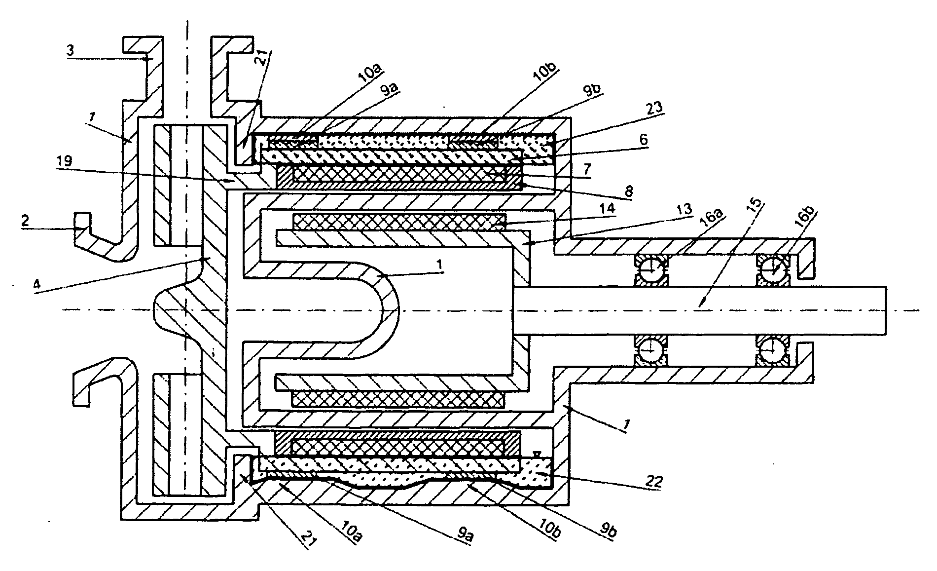
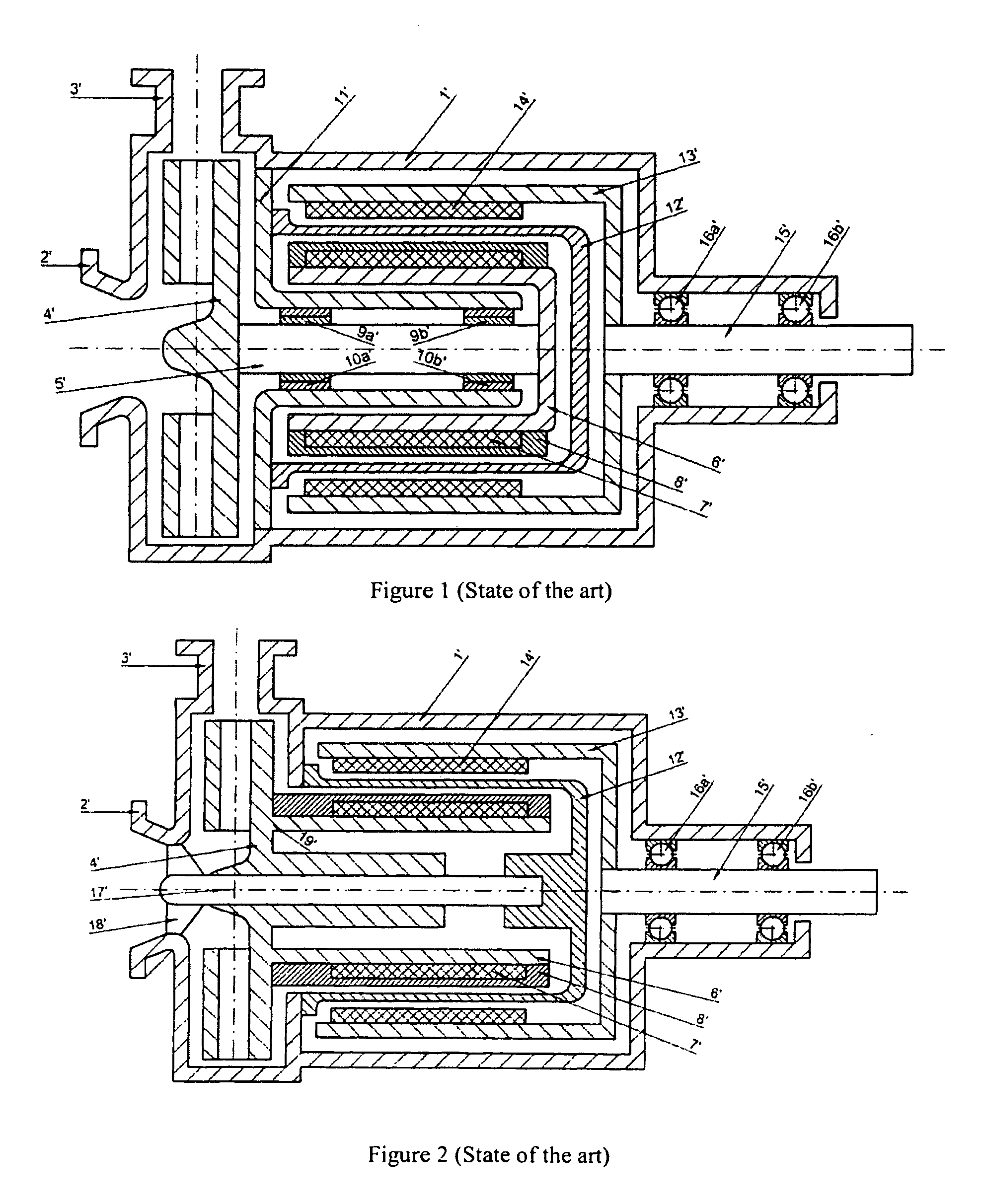
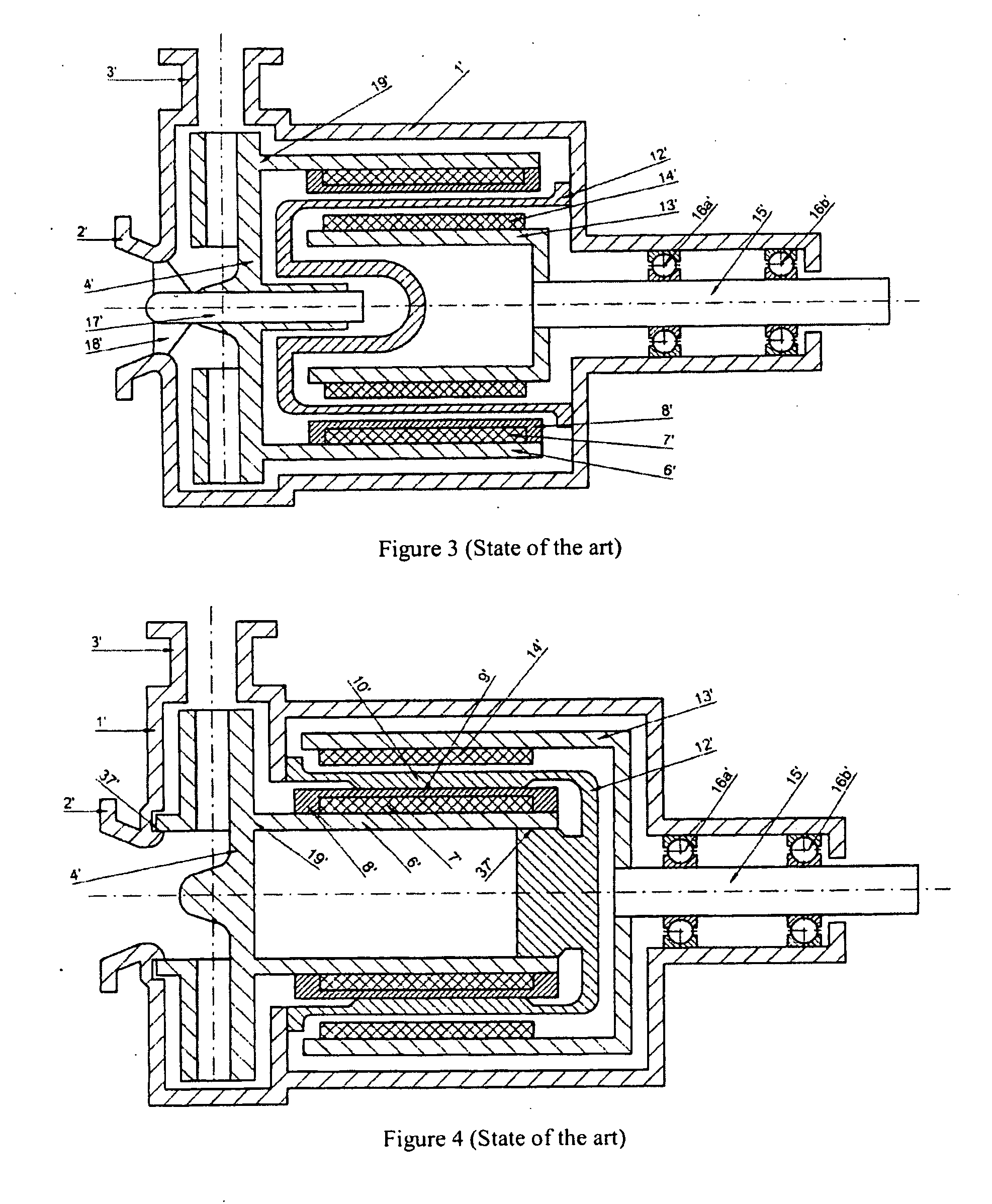
[0049]All embodiments have a pump housing 1 with a suction port 2 and a pressure port 3, wherein a pump blade wheel 4 is mounted coaxial to the suction port and is fluidically connected to the pressure port 3 in the radial direction. The pump blade wheel 4 has, on the drive side, a magnetic rotor 6, with which it forms a blade wheel-magnetic rotor unit that is open toward the drive side. On its outer periphery, this unit has the rotating part 9 of a floating bearing, while the stationary part 10 of this floating bearing is arranged on the inner wall 20 of the pump housing 1. On the radial inside, the magnetic rotor 6 carries permanent magnets 7. These stand opposite permanent magnets 14 with a radial distance and these magnets are arranged on the outer surface of an approximately pot-shaped magnetic driver 13. Between the magnetic rotor and the magnetic driver there is a separating wall in all embodiments, optionally in the shape of a so-called slotted pot 12, with this wall keeping...


PUM


Abstract

The invention relates to a magnetic coupling pump, with the motor-driven part of the magnetic coupling lying radially inward and the radially outward part of the coupling, together with the pump rotor, having a floating fit in the pumped fluid such that the rotating part of the floating bearing is also radially arranged over the outer magnets. The wall of the pump housing can itself be embodied as the stationary part of the floating bearing with the possibility of direct external access (lubrication, sensor mechanism) and an effective convectional cooling. Dry running on operational faults can be avoided by means of the floating bearing arranged far to the outside, as the damaging gas fraction collects in the radial interior of the pump and remaining traces of liquid are continuously driven outwards and thus contribute to bearing lubrication. By means of an additional annular barrier, the loss of residual fluid can be prevented. The disclosed novel floating bearing permits a large volume separating case which itself permits components of the roller bearings of the motor-driven magnetic coupling section so much installation space that the axial installation length of the complete pump can be significantly shortened.

Description

CROSS-REFERENCE TO RELATED APPLICATIONS[0001]This application is a national stage entry of international application number PCT / EP2007 / 002814, having international filing date Mar. 29, 2007, which was not published in English, which claims priority to German patent application number DE202006005189.9, filed Mar. 31, 2006, the entirety of which are hereby incorporated by reference.FIELD OF THE INVENTION[0002]The invention relates to a rotary pump with the features of the preamble of Claim 1, as is known from EP-B1-0171515.BACKGROUND[0003]Rotary pumps with a magnetic coupling represent an important type of machine used industrially for delivering liquids. Relative to simpler rotary pumps with a floating ring seal, they have the advantage of a hermetic seal of the pumping space. This can appear to be favorable, especially for delivering aggressive or toxic liquids.[0004]In most cases, coaxial rotating couplings with a radial arrangement of the magnets and corresponding radial magnetic ...

Claims


Application Information

Patent Timeline
IPC IPC(8): F04D13/02F04D29/04
CPCF04D29/048F04D29/049F04D13/027F04D13/026F04D13/025F04D13/02
Inventor PLATT, WERNER
Owner H WERNERT & CO
Why Eureka
Try Eureka