
Method of fabricating an optical analysis device comprising a quantum cascade laser and a quantum detector

a quantum cascade laser and optical analysis technology, applied in semiconductor lasers, instruments, lasers, etc., can solve the problems of limiting the functionalities, forming from an assembly of components, and not being able to imag

Inactive Publication Date: 2010-02-04
THALES SA
View PDF11 Cites 38 Cited by
  • Summary
  • Abstract
  • Description
  • Claims
  • Application Information

AI Technical Summary

Benefits of technology

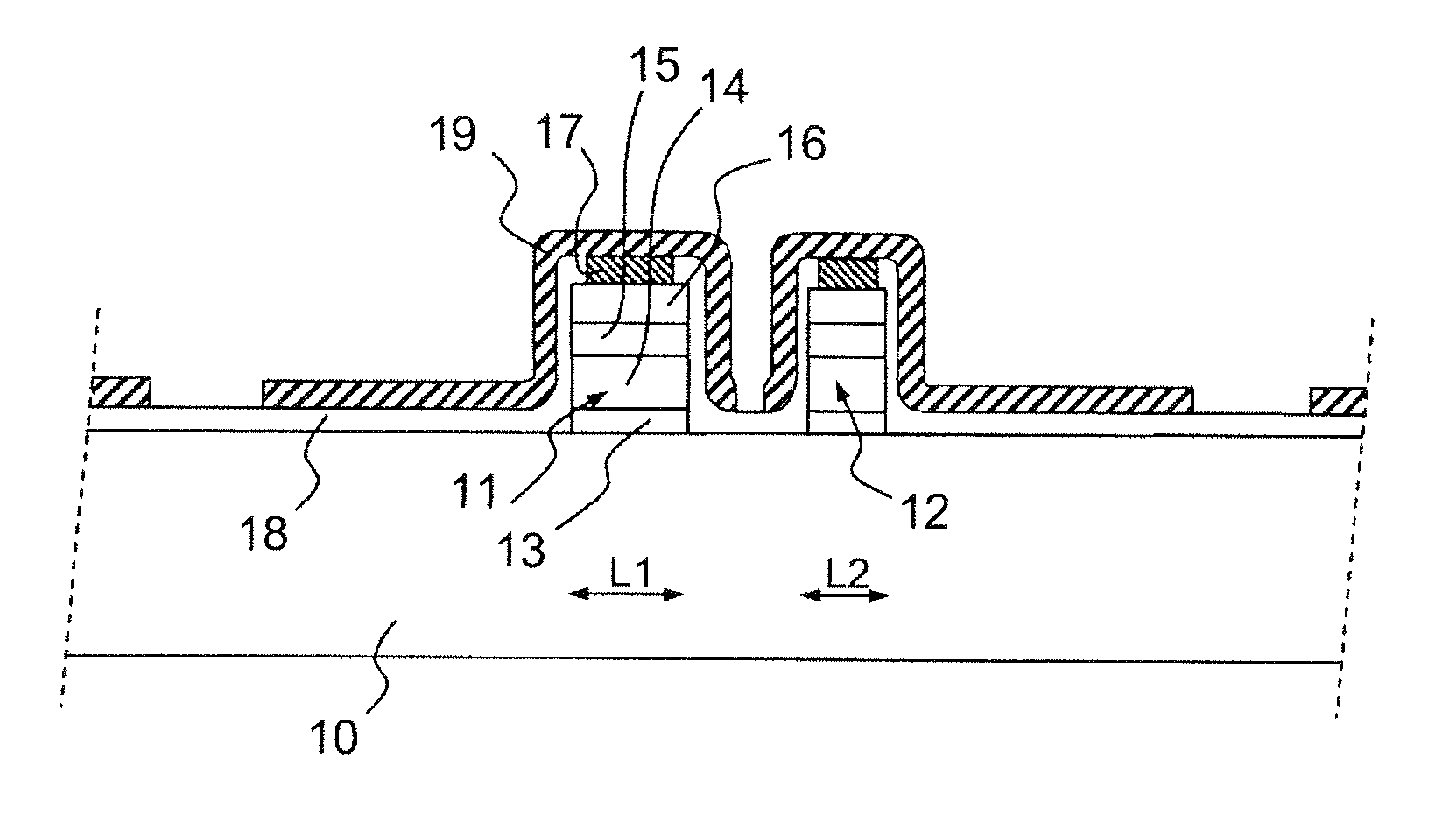
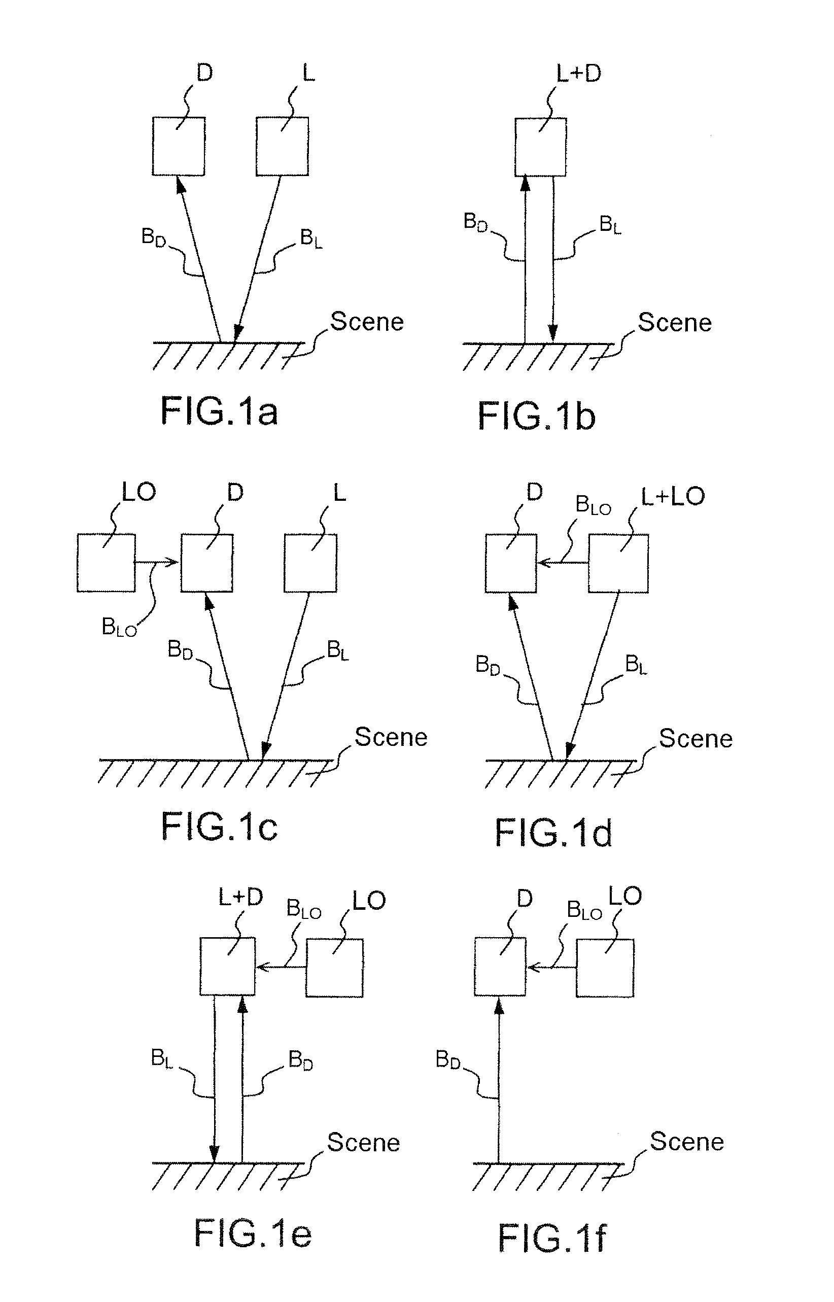
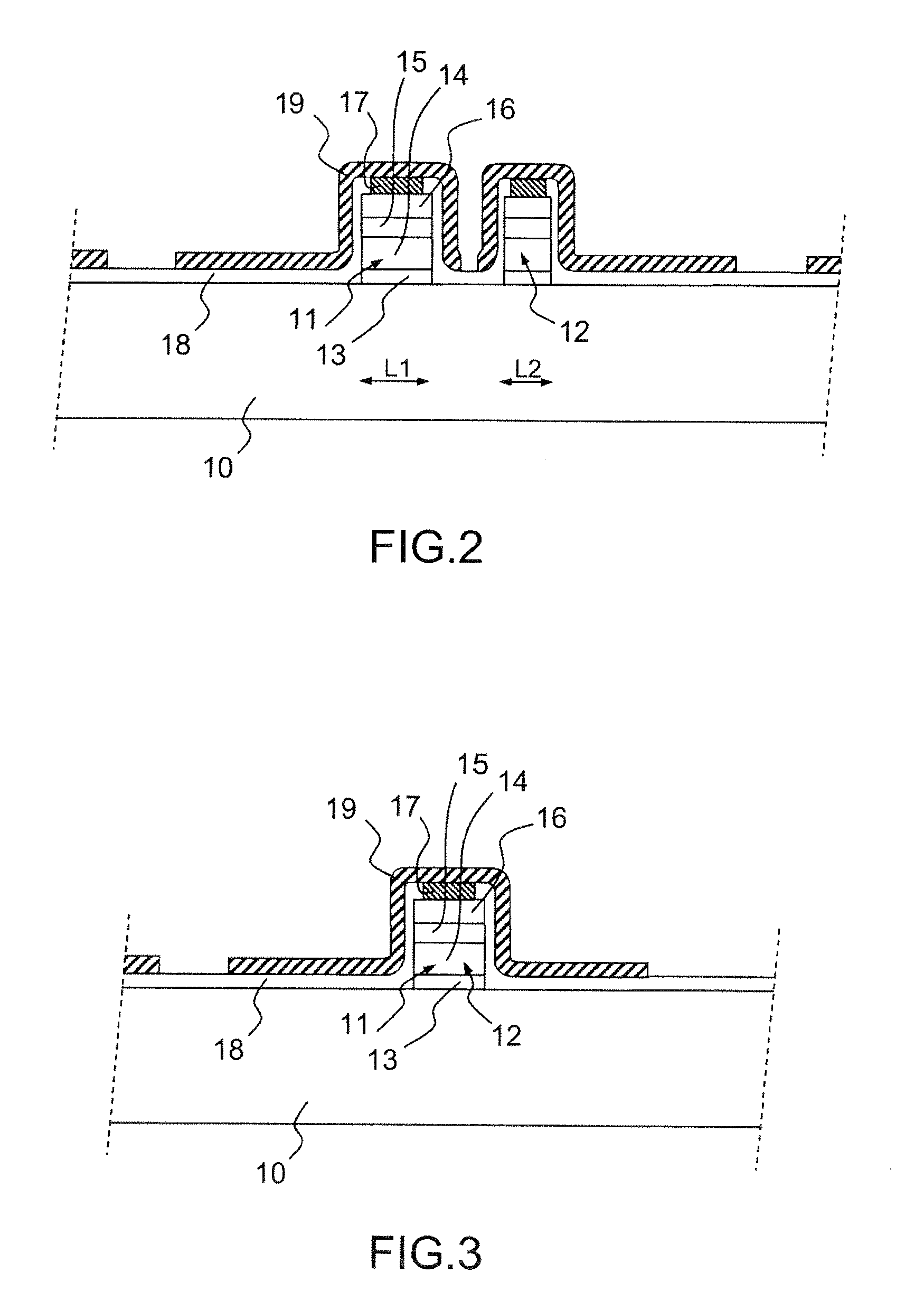
The present invention proposes a method of fabricating an optical device for analyzing a scene by integrating a detector and a laser source into a monolithic device during design. The device includes a stack of semiconductor layers grown epitaxially on the surface of a semiconductor substrate, with certain layers being doped. The device also includes a first quantum cascade laser emission device emitting an analysis beam in the mid-infrared or far-infrared, and a second quantum detector device capable of detecting a beam backscattered by the scene to be analyzed. The analysis beam can be directed towards the scene or both the detector and the scene. The method can also include the production of a local oscillator device for performing heterodyne detection. The device can be produced within a single stack of layers or at different locations in the stack. The optical device can be used for analyzing gaseous species or can be designed for multispectral analysis. The variation in specific wavelength can be obtained by varying the characteristics of each emission device.

Problems solved by technology

A major drawback of these detection systems is that they are formed from an assembly of components (laser, cavity or mirrors, detector) that are relatively complex to fabricate, assemble and implement.
However, this solution remains an assembly of components and limits the functionalities (no imaging is possible).

Method used


Image

  • Method of fabricating an optical analysis device comprising a quantum cascade laser and a quantum detector
  • Method of fabricating an optical analysis device comprising a quantum cascade laser and a quantum detector
  • Method of fabricating an optical analysis device comprising a quantum cascade laser and a quantum detector

Examples


Embodiment Construction

[0032]The invention will be described within the context of detecting gas molecules, but it could equally well apply both to the detection of other types of molecular species in a given medium or the analysis of any type of surface or scene, from which it is desired to extract information using a beam backscattered by said scene.

[0033]In general, the fabrication method of the invention makes it possible to produce an integrated device which is simple and robust compared with the current systems and is based on a well-established understanding of controlling the epitaxial growth of Ill-V materials.

[0034]The method consists of using the technological process for such growth in order to produce an integrated LIDAR system comprising at least one emitter and at least one detector integrated into one and the same component.

[0035]The method of fabricating the detection device according to the invention makes it possible to produce, on a single semiconductor substrate, a structure such that...


PUM


Abstract

The invention relates to a method of fabricating an optical device for analysing a scene, comprising an emitter and a detector in the mid-infrared or far-infrared, characterized in that it comprises:the production of a stack of semiconductor layers grown epitaxially on the surface of a semiconductor substrate, certain layers of which are doped;the production of a first, quantum cascade laser emission device (L) emitting an analysis beam in the mid-infrared or far-infrared, from a first level called the emission level, into the stack of semiconductor layers; andthe production of a second, quantum detector device (D) capable of detecting a beam backscattered by the scene to be analysed, at the same level in the stack as the emission level.

Description

PRIORITY CLAIM[0001]This application claims priority to French Patent Application Number 08 04413, entitled Method Of Fabricating An Optical Analysis Device Comprising A Quantum Cascade Laser And A Quantum Detector, filed on Aug. 1, 2008.TECHNICAL FIELD[0002]The field of the invention is that of spectroscopic mid-infrared or far-infrared remote detection devices.BACKGROUND ART[0003]Currently, there are optical systems for detecting particular molecular entities present in a given environment, for example gas molecules, used for process control, environment control or medical analysis, which employ a laser and a detector.[0004]Notably, there are backscattering devices, usually called LIDAR (Light Detection And Ranging) devices, which represent key systems in determining the spatial distribution and optical properties of aerosols and clouds. Such information is fundamental in many meteorological and environmental applications in the laboratory or in the field.[0005]In said systems, th...

Claims


Application Information

Patent Timeline
Patent Type & Authority Applications(United States)
IPC IPC(8): H01L21/00
CPCB82Y20/00G01S7/4811H01S5/3402H01L31/173H01S5/0262H01L31/035236
Inventor BERGER, VINCENTCARRAS, MATHIEU
Owner THALES SA
Learn More