Fabric web having photocatalysis-based pollution control properties

a technology of photocatalysis and fibers, applied in the direction of weaving, water treatment compounds, separation processes, etc., can solve the problems of difficult to achieve the adhesion and deposit of photocatalytic particles on the surface of optical fibres, and achieve the effect of optimum mechanical strength and optimum surface uniformity

Inactive Publication Date: 2010-02-04
BROCHIER TECH
View PDF5 Cites 24 Cited by
  • Summary
  • Abstract
  • Description
  • Claims
  • Application Information

AI Technical Summary

Benefits of technology

[0023]In this case, the optical fibres can be woven in places with the binding yarns, with the optical fibres being substantially positioned in a plane which is parallel to the plane defined by the binding yarns on which the spread coating is deposited. Thus, the spread coating is not deposited on the optical fibres, only on one of the sides of the web which is fo

Problems solved by technology

However, depositing the photocatalytic particles on the surface of the optical fibres and

Method used


Image

  • Fabric web having photocatalysis-based pollution control properties
  • Fabric web having photocatalysis-based pollution control properties
  • Fabric web having photocatalysis-based pollution control properties

Examples


Embodiment Construction

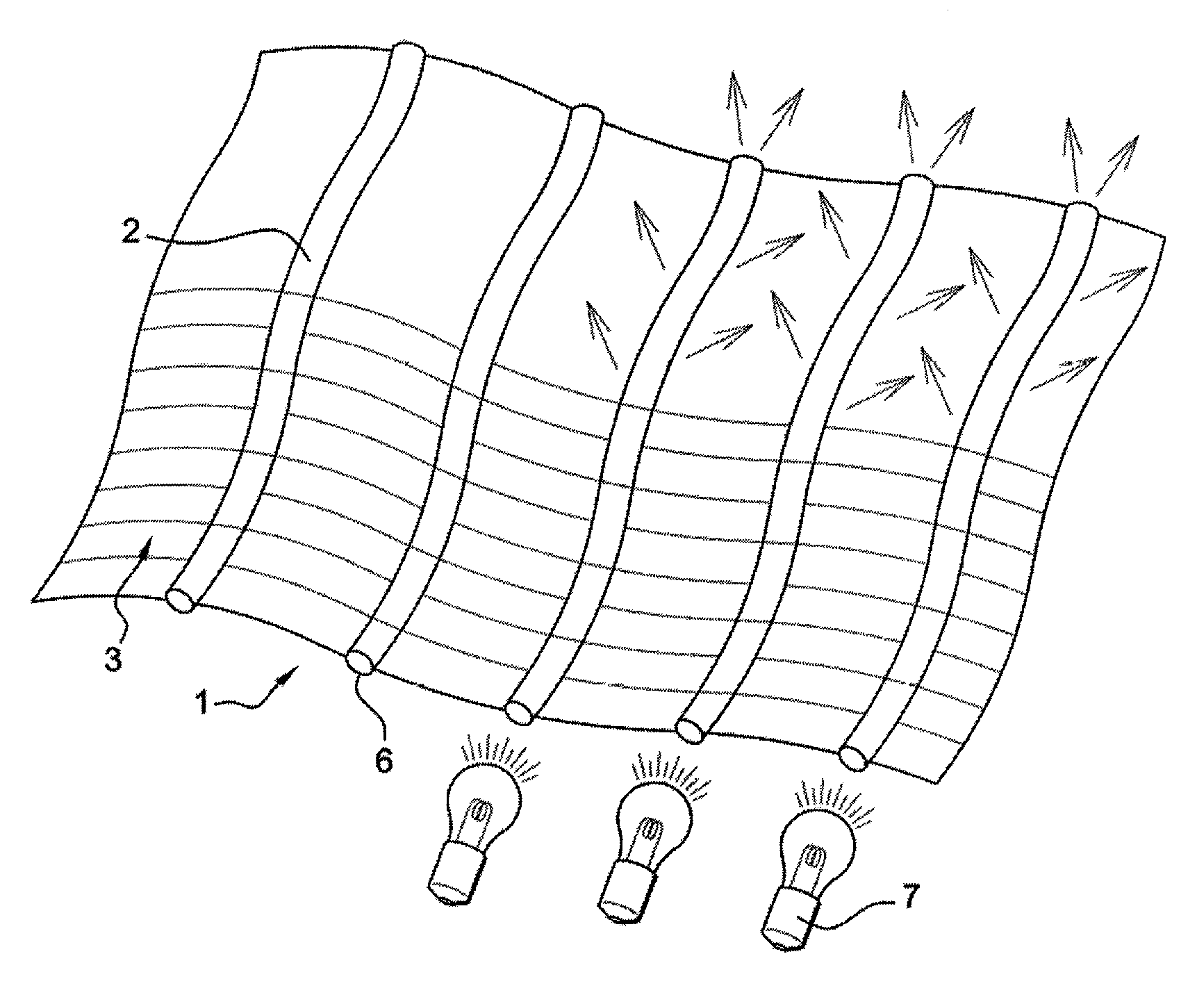
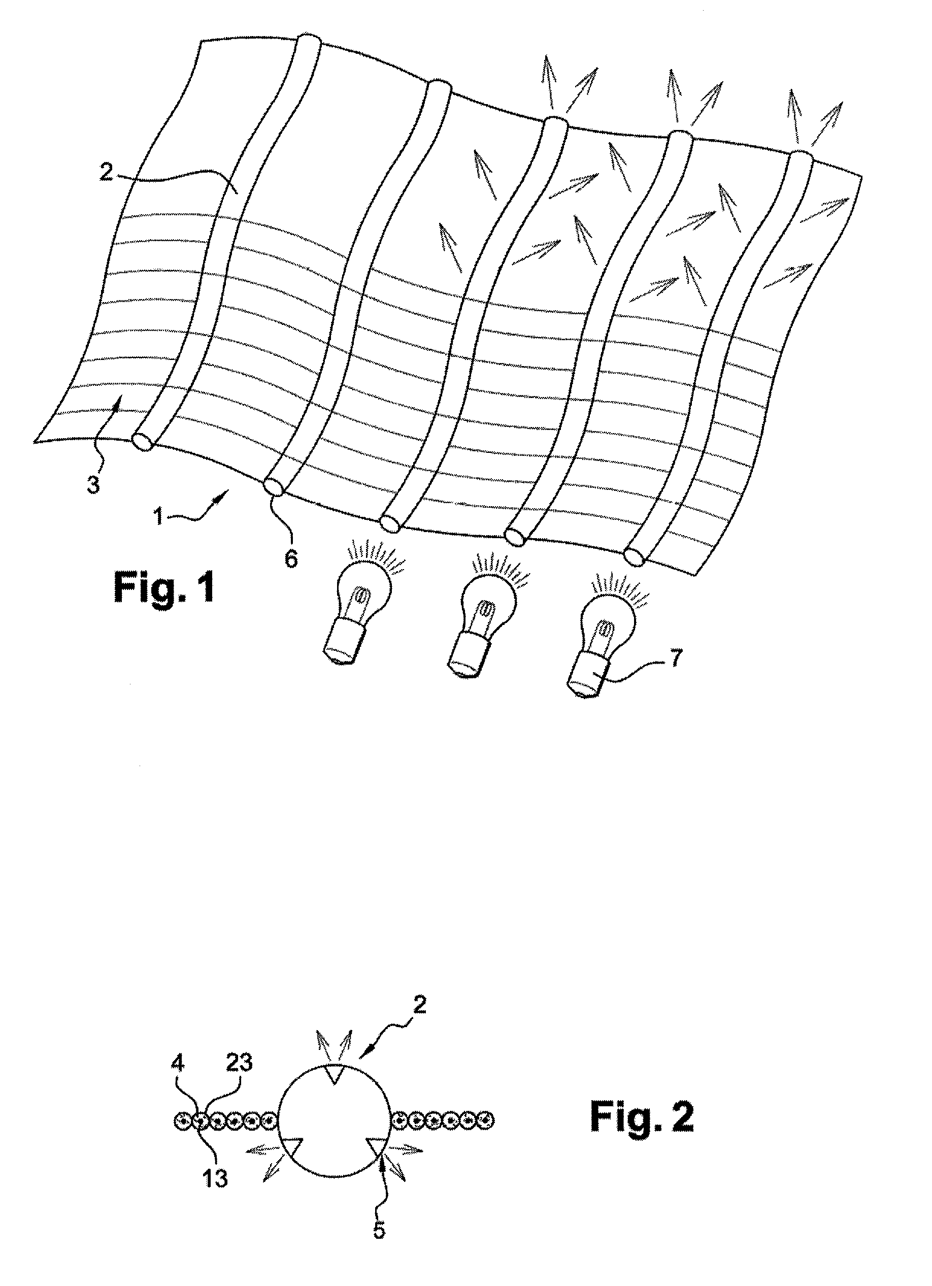
[0038]As stated above, the invention relates to a fabric web such as that shown in FIG. 1. The fabric web (1) comprises warp and / or weft optical fibres (2) woven with warp and / or weft binding yarns (3). Such a fabric web makes it possible to distribute optical fibres (2) uniformly in a plane in which they are parallel to each other. These optical fibres (2) are treated so that they transmit light and emit light sideways from their outer cylindrical surface. This treatment of optical fibres (2) produces a plurality of invasive alterations on their surface.

[0039]In addition, one or more light sources (7) is / are positioned facing the free ends (6) of optical fibres (2) which may or may not be bunched. The light emitted sideways by optical fibres (2) can be transmitted from one edge of fabric web (1) to the other at right angles to each of these edges as well as inside the fabric web.

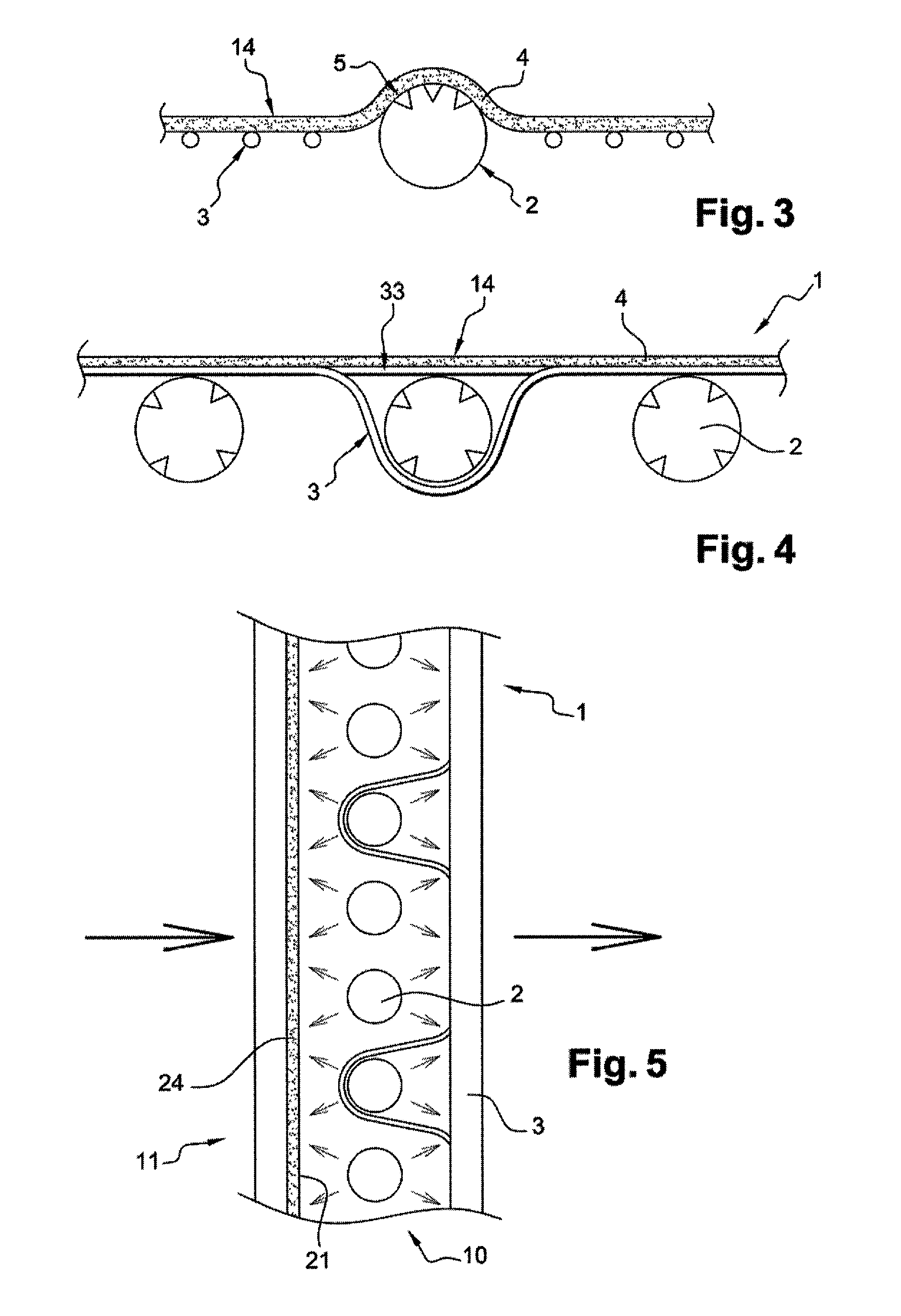
[0040]This layout makes it possible to activate the photocatalytic particles which are placed on one of ...


PUM

PropertyMeasurementUnit
Photocatalytic propertiesaaaaaaaaaa
Areaaaaaaaaaaa
Semiconductor propertiesaaaaaaaaaa

Abstract

Fabric web comprising warp and/or weft optical fibres woven with warp and weft binding yarns, in which said optical fibres can emit light sideways characterised in that the surface of the binding yarns is provided with photocatalytic particles and in that said optical fibres include invasive alterations, whereby the free ends of said optical fibres can be positioned facing a light source in order to transmit light and emit light sideways at the aforementioned alterations so as to activate the photocatalytic particles.

Description

CROSS REFERENCE TO RELATED APPLICATIONS[0001]This application is a National Stage filing under 35 U.S.C. §371 of PCT Application No. PCT / FR2007 / 052594, filed Dec. 20, 2007. This application also claims the benefit of French Application No. 0655665, filed Dec. 20, 2006. The entirety of both applications is incorporated herein by reference.[0002]The invention relates to the field of controlling pollution in fluids such as foul air or waste water. In fact, a pollution-control fabric web can be used in open spaces charged with carbon dioxide or other organic particles suspended in air. It can also be used in a plant for cleansing or treating waste water in order to control pollution in water which flows tangentially relative to the fabric web and / or through interstices in the fabric web at points where the yarns which constitute it intersect.[0003]It relates more especially to a fabric web provided with optical fibres in order to transmit light.DESCRIPTION OF THE PRIOR ART[0004]Generall...

Claims


Application Information

Patent Timeline
IPC IPC(8): B32B5/02B32B27/02B32B27/34B32B27/32B32B27/36D03D15/00
CPCB01D53/885B01D2255/802C02F1/325C02F1/725C02F2201/3224G02B6/001C03C19/00C03C25/101C03C25/106C03C25/68C02F2305/10C03C25/47Y10T442/20Y10T442/2861Y10T442/2893Y10T442/291Y10T442/2918Y10T442/3049Y02W10/37
Inventor BROCHIER, CEDRICMALHOMME, DELPHINEDEFLIN, EMMANUEL
Owner BROCHIER TECH
Why Eureka
Try Eureka