Carbon-Kevlar uni-body rocket engine and method of making same

a rocket engine and carbon-kevlar technology, applied in the field of rocket engines, can solve the problems of increasing the mass of the spaceship, sudden all-over ignition, and hard start, and achieve the effects of reducing the number of oxidizers

Inactive Publication Date: 2010-02-11
OEHRLEIN ROBERT
View PDF6 Cites 13 Cited by
  • Summary
  • Abstract
  • Description
  • Claims
  • Application Information

AI Technical Summary

Benefits of technology

[0018]The engine of the invention preferably is regeneratively cooled and has one or more oxidizer tubes connected between an oxidizer ring at the bottom of the exhaust nozzle and a source of oxidizer. The tubes are integrally connected at one end to the oxidizer ring and at the other end are integrally connected to mounting brackets that are integrally connected to the combustion chamber in bridging relationship to the throat. In addition to supplying oxidizer to the oxidizer ring, the oxidizer tubes also reinforce the engine, especially across the throat, its narrowest and potentially weakest point.
[0019]In the engine of the invention the lower end of the oxidizer tube is connected to the oxidizer ring in a generally tangential direction for improved flow, and in preferred embodiments multiple oxidizer tubes are used for more efficient and uniform distribution of the oxidizer in the flow channels between the skins of the uni-body and to enable supply of multiple types of oxidizer from different sources. The engine uses outside ai...

Problems solved by technology

In spite of the presence of oxygen at low altitudes, conventional space ships, regardless of the type of propellant they burn, carry the required oxygen on-board, adding significantly to the mass of the spaceship.
When the shower of sparks touches the fuel-oxidizer mixture, there is a sudden all-over ignition.
This is called a hard start and is dangerous and stressful on the e...

Method used


Image

  • Carbon-Kevlar uni-body rocket engine and method of making same
  • Carbon-Kevlar uni-body rocket engine and method of making same
  • Carbon-Kevlar uni-body rocket engine and method of making same

Examples


Embodiment Construction

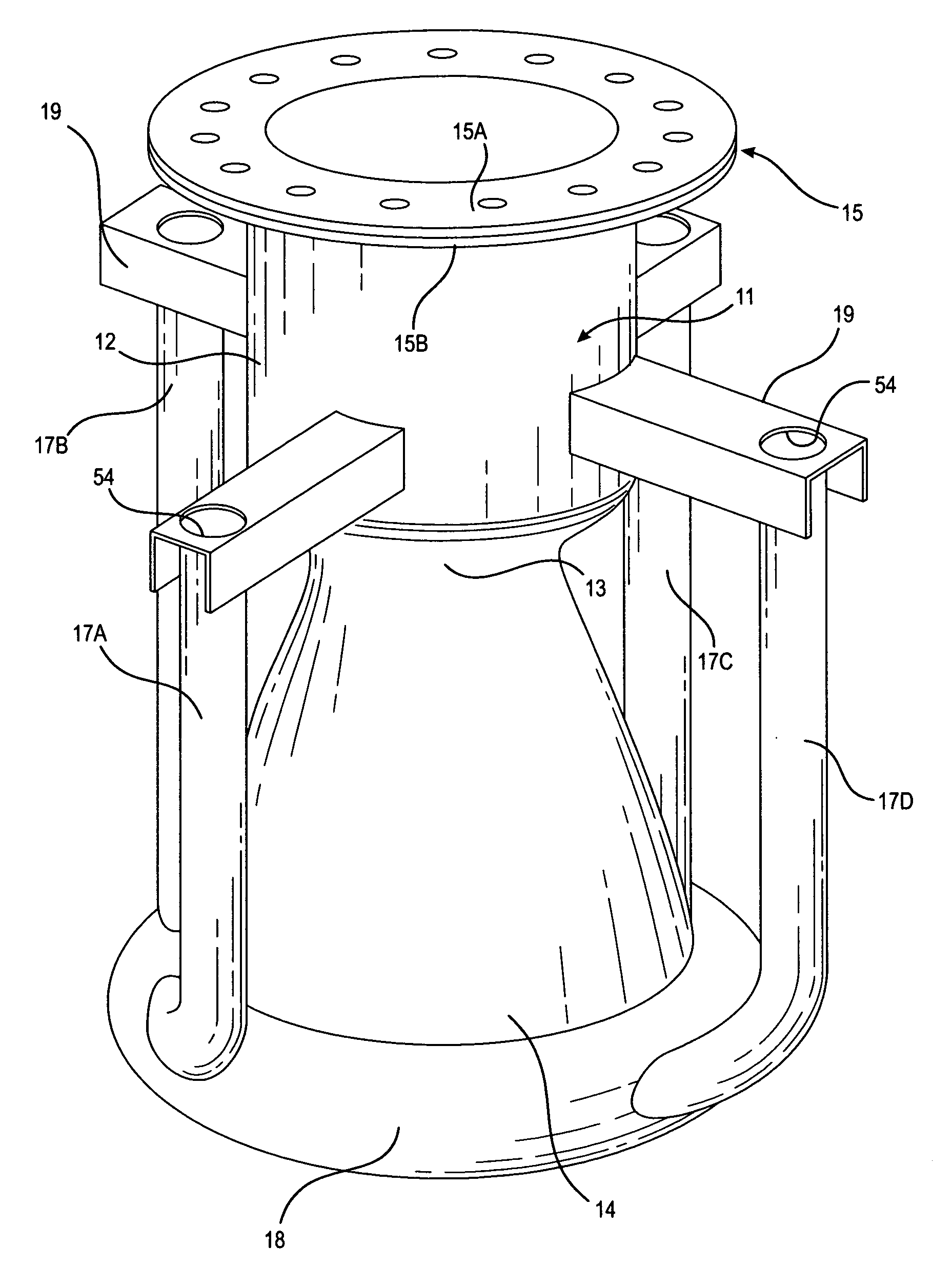
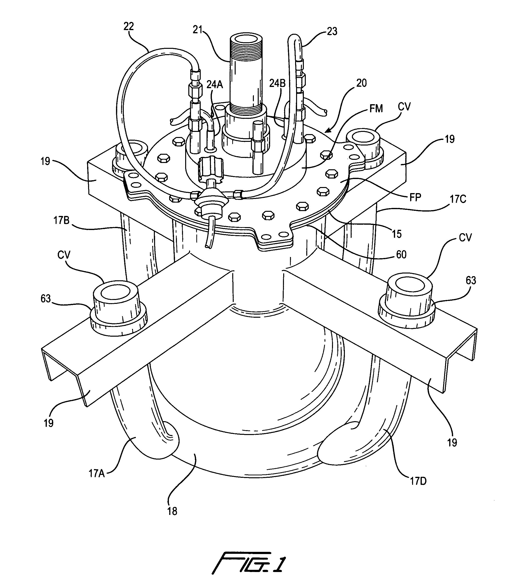
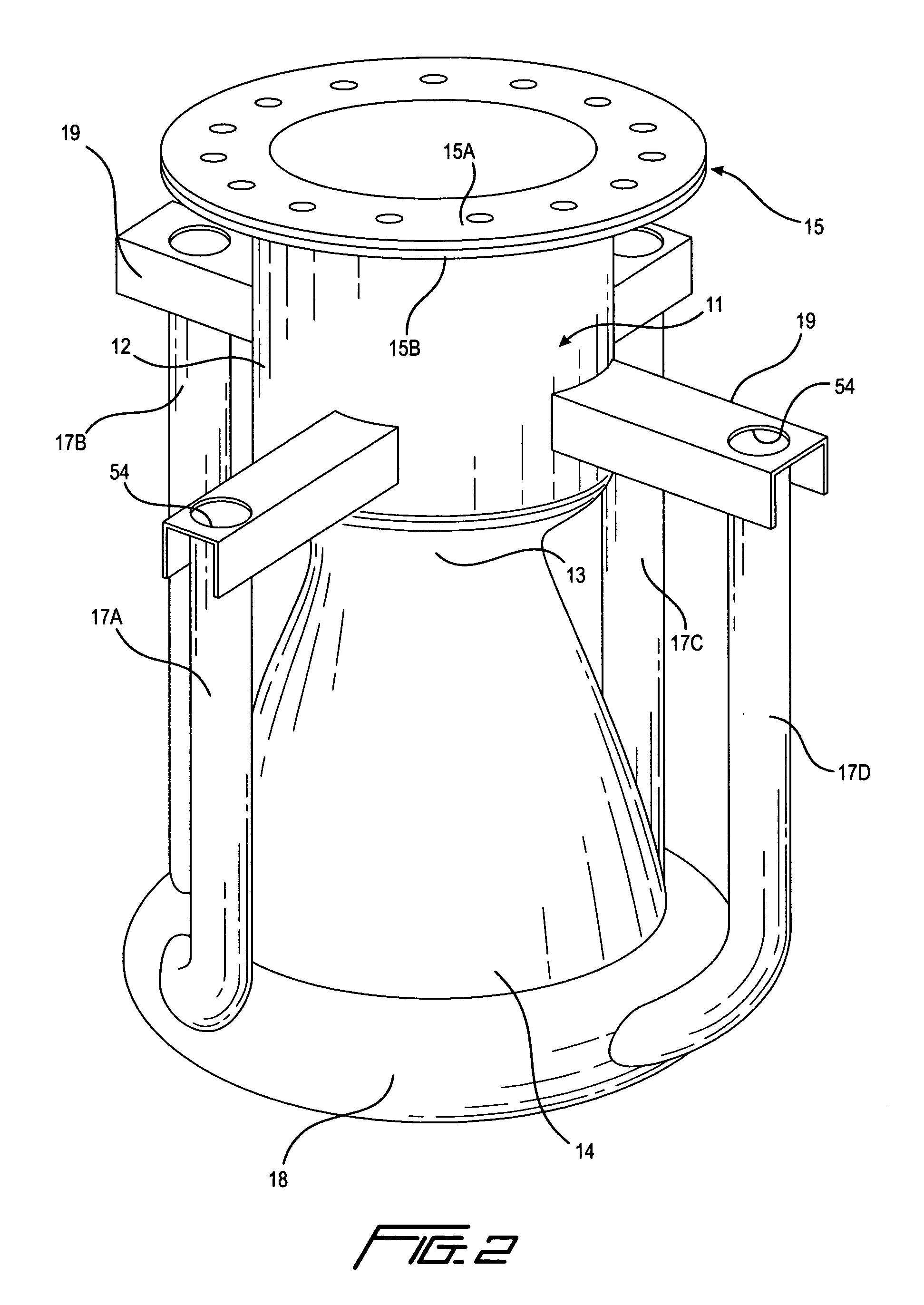
[0045]An integrally formed one-piece rocket engine according to the invention is indicated generally at 10 in FIGS. 1 and 2. The engine 10 comprises an engine body 11 having a combustion chamber 12 of substantially cylindrical shape, a reduced diameter throat 13, and an outwardly flared exhaust bell or nozzle 14, with a radially outwardly directed upper flange 15 on its upper end and a radially outwardly directed bottom flange 16 on its lower end. The engine body is of substantially conventional shape is but formed integrally as one piece. Four oxidizer tubes 17A, 17B, 17C and 17D are provided in this embodiment, extending longitudinally of the engine and connected tangentially at their lower ends to an oxidizer ring 18 formed integrally on the exhaust bell at its bottom end, and connected at their upper ends to mounting brackets 19 that are in turn integrally connected to the combustion chamber just above the throat. This arrangement not only permits supply of oxidizer to multiple ...


PUM

PropertyMeasurementUnit
Fractionaaaaaaaaaa
Shapeaaaaaaaaaa

Abstract

A rocket engine has spaced apart inner and outer skins each unitarily formed in one piece from carbon fiber fabric. The inner skin is formed on a two-part mold that is separated and removed from the inner skin after it is cured. An oxidizer ring encircles the bottom of the engine and is in flow communication with flow channels between the skins. Oxidizer tubes are connected at one end to the ring and at their other end to support brackets on the engine. The oxidizer ring is formed as an integral part of the engine by extending the outer skin over an inflatable mold, which is deflated and removed from the ring after the ring is cured. The oxidizer tube is formed on a mold with a rigid spine that holds the shape of the mold until the oxidizer tube is cured. The spine and the mold are then removed.

Description

[0001]This application is a continuation-in-part of U.S. application Ser. No. 12 / 077,758, filed Mar. 21, 2008, the entire disclosure of which is incorporated herein by reference.TECHNICAL FIELD[0002]This invention relates generally to rocket engines, and more particularly to a reinforced, regeneratively cooled, carbon-Kevlar uni-body rocket engine with a redundant soft-start ignition, and to the method of making the same.BACKGROUND ART[0003]Conventional rockets take off vertically and use a propellant that is a chemical mixture of fuel and oxidizer burned to produce thrust. The single heaviest item carried by a spaceship is the propellant, of which the oxidizer comprises the majority.[0004]The greatest rate of oxygen consumption for a rocket engine is relatively close to the ground, where atmospheric air up to about 40,000 feet contains a relatively large amount of oxygen. In spite of the presence of oxygen at low altitudes, conventional space ships, regardless of the type of propel...

Claims


Application Information

Patent Timeline
IPC IPC(8): F02K9/00B32B37/10
CPCB29C70/446B29K2277/10B29K2707/04F05D2300/603F02K9/972F05D2230/21F02K9/64
Inventor OEHRLEIN, ROBERT
Owner OEHRLEIN ROBERT
Why Eureka
Try Eureka