Unitized penile erection system and tissue expander

a tissue expander and penile erection technology, applied in the field of implantable penile prostheses, can solve the problems of inability to fully function, inconvenient surgical approach to erectile dysfunction, and inability to produce rigidity for erection, and achieve the effect of natural and full penis feeling

Inactive Publication Date: 2010-02-11
WALCH JOHN R
View PDF17 Cites 14 Cited by
  • Summary
  • Abstract
  • Description
  • Claims
  • Application Information

AI Technical Summary

Benefits of technology

[0010]It is a further object of the present invention to provide a unitized implantable inflatable prosthetic penile device or system that requires a smaller volume of fluid transfer to inflate the prosthesis.
[0011]It is a still further object of the invention to provide a unitized implantable inflatable prosthetic penile device or system that requires a smaller volume of fluid transfer to inflate the prosthesis and that provides a more natural and full feel of the penis in its flaccid state.
[0012]In accordance with the illustrative embodiments demonstrating features and advantages of the present invention, there is provided a unitized surgically implantable device comprised of a hydraulically activated extendable cavernosal component and a manually controlled fluid transfer system compos

Problems solved by technology

This results in the inflation of the prostheses and produces rigidity for an erection.
The surgical approach to erectile dysfunction has inherent risks including the erosion of the tissues surrounding the devices when constant pressure due to the rigidity of the device is applied to these tissues.
A second risk is that of infection, a great deal of which is related to handling of the scrotal tissues required for the remote implantation of devices, the scrotum being in close proximity to the perineal structures and anal region which is difficult to sanitize for surgical procedures.
Placement of a remote reservoir within the pre-peritoneal and/or the intra-abdominal cavities carries the risks of intra-abd

Method used


Image

  • Unitized penile erection system and tissue expander
  • Unitized penile erection system and tissue expander
  • Unitized penile erection system and tissue expander

Examples


Embodiment Construction

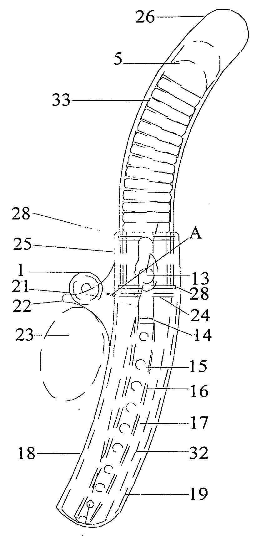
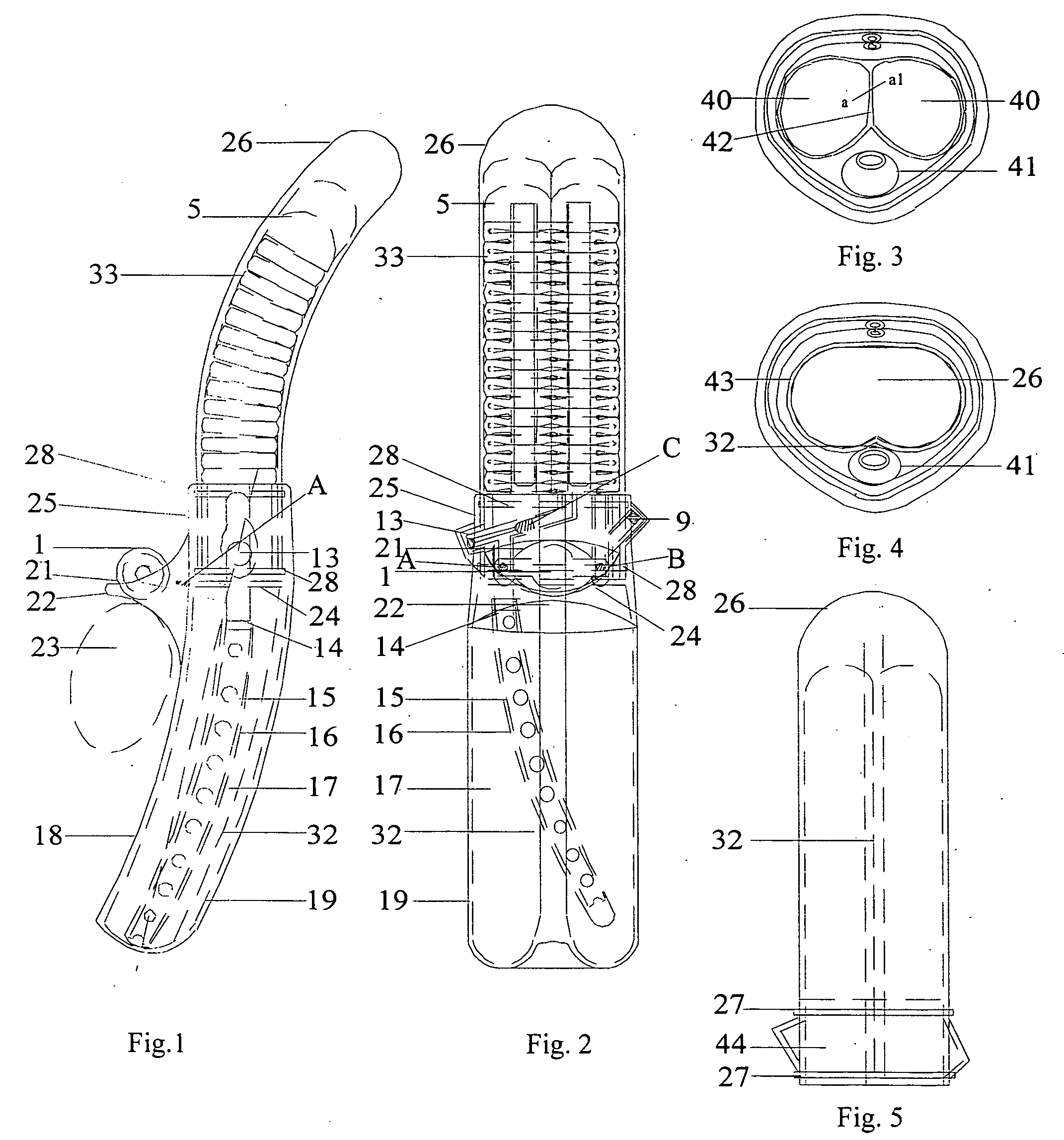
[0036]Referring now to the drawings in detail wherein like reference numerals have been used throughout the various figures to designate like elements, there is shown in FIGS. 1 and 2 a unitized implantable inflatable prosthetic penile device or system constructed in accordance with the principles of the present invention. The implantable penile device as depicted in a right lateral aspect in FIG. 1 has been designed to be placed in an anatomical position in relation to the symphysis pubis 23 that corresponds to the normal position of the corpus cavernosum 40, corpus spongiosum 41, and the anchoring crura of the cavernosal system which are located below the sysmphysis pubis 23, and follows along the bony ischial rami of the male pelvis. (See FIGS. 3 and 4.)

[0037]Referring to FIG. 3, it can be seen that the fused, unitized design of the invention would require incision, designated by line a-a1, of the fascial septae of the adjacent cavernosal fascial compartments 42 surrounding the p...


PUM


Abstract

A surgically implantable device is a single unit comprised of a hydraulically activated extendable cavernosal component and a manually controlled fluid transfer system composed of a pump. Flow from the pump is directed by a one way valve interposed between a bypass from an included elastic reservoir, the pump and a second one way valve interposed between the pump and the cavernosal unit. A manually controlled release valve, interposed between the outlet of the cavernosal unit and the reservoir, permits de-activation of the cavernosal unit and returns fluid to the reservoir. These components are housed by a molded tailpiece which stabilizes the device against the symphysis pubis, positions the cavernosal implant properly within the shaft of the penis and presents the controls for easy access. An access port permits adjustment of the fluid volume. The unit has utility as a tissue expander and penile re-construction in event of congenital or traumatic deformity.

Description

FIELD OF THE INVENTION [0001]The present invention relates to systems for treating erectile dysfunction and other urological disorders in the human male. In particular, the invention relates to implantable penile prostheses.BACKGROUND OF THE INVENTION [0002]The evolution of the interventional treatment of erectile dysfunction has a colorful history. Initial attempts centered around external splints. Overlapping efforts then included trusses and external constriction about the root of the male organ and vacuum devices designed to fill the organ passively combined with a circular constrictor, again placed at the root of the male organ.[0003]Surgically implantable sphincter systems with inflatable constrictors placed at the root of the organ or each arm of the cavernosa have also been offered. Additional ideas included implantable rigid rods and malleable rods. Commensurate with these, various hydraulically activated fully implantable devices requiring multiple insertion sites show a m...

Claims


Application Information

Patent Timeline
IPC IPC(8): A61F5/00
CPCA61F2/26
Inventor WALCH, JOHN R.
Owner WALCH JOHN R
Why Eureka
Try Eureka