Desalination Method and System Using Compressed Air Energy Systems

a technology of compressed air and energy systems, applied in the field of desalination systems, can solve the problems of insufficient amount of fresh drinking water available, inconvenient or possible transportation of water, and insufficient supply of fresh drinking water, etc., and achieve the effect of reducing the temperature of seawater

Inactive Publication Date: 2010-02-18
ENIS BEN M +1
View PDF49 Cites 80 Cited by
  • Summary
  • Abstract
  • Description
  • Claims
  • Application Information

AI Technical Summary

Benefits of technology

[0028]3. As the seawater droplets begin to mix with the chilled air, and freeze, due to heat exchange, pure water ice crystals begin to form, which begin to separate from the salty brine solution. Over time, i.e., less than a few seconds, the frozen ice particles begin to fall to the bottom of the chamber, where due to heat exchange the temperature of the air is warmer, and wherein the air and the growing deposit of ice particles at the bottom eventually reach an equilibrium temperature that is preferably just above the eutectic temperature. Then, the lower density ice particles begin to float and coalesce on top of the higher density salty brine solution that collects at the bottom, and form an ice / snow mass that continues to enlarge and float on top of the salty brine solution, wherein any higher density salt brine continues to separate from the ice particles and runoff down the sides of and through the channels and voids that exist in the ice / snow mass. A fresh water wash column involving a spray of water can be used to help facilitate the runoff of the brine from the ice / snow mass to help clean the ice mass further. Note: The density of the brine may be between 1.35 gm / cc when concentrated and 1.025 gm / cc in seawater; whereas the density of pure water is 1 gm / cc; the density of fresh water ice is 0.917 gm / cc; and the density of snow is less than 0.l gm / cc. Thus the high density brine flows out between the pores in the ice / snow mass and over the interstices between the ice fragments.
[0049]The mass of ice particles which is removed can then be melted, to produce fresh water at the bottom of a holding tank. Fresh water at relatively warm temperatures, in this case, at plus 60 degrees F., can be sprayed down like a wash column onto the ice particles, to rinse the ice, and cause the ice to melt. Alternatively, or in conjunction with the rinse water, local warm air can be brought into the holding tank, to further assist in melting the ice particles. As the ice melts, the fresh water droplets can pass through the perforations in the basket, and collect at the bottom of the holding tank, in the form of chilled fresh drinking water. More than one basket can be used so that the desalination and melting processes do not need to be interrupted while removing each basket from the chamber. Other means of removing and melting the ice mass, such as using a drop down door, that allows the ice mass to drop onto a conveyor, so that it can be moved to where it can more easily be melted, can also be provided.

Problems solved by technology

Nevertheless, there are many geographical areas where it is not as convenient or possible to transport water to where it is needed, on a cost effective basis.
These areas include far away regions in the mountains, faraway rural areas, and islands in the ocean, where it might be cost prohibitive to install long pipelines or aqueducts to transport water to those areas.
Ironically, many of these areas are located close to the ocean, or other salt water bodies, where seawater is available, but where the amount of fresh drinking water available may be insufficient to meet the demand.
While these methods are highly successful and effective in being able to remove contaminants from the seawater, one of the most significant disadvantages of these methods is the high cost of operation, including the high cost of the energy needed to heat the seawater, and / or reduce the pressure, to boil it.
Because of these costs, these methods are often used only when fresh drinking water is not available, or could not be made available at a lower cost.
While reverse osmosis has been shown to be economical in terms of its relatively low energy consumption rate, the process typically has a significantly higher upfront investment cost compared to most thermal methods.
There is also a relatively high cost associated with the replacement cost of membrane material, due to limited membrane life.
This process has some of the same drawbacks as reverse osmosis, in that the upfront capital costs can be prohibitive.
This process and its potential has been investigated due to its higher efficiencies when compared to reverse osmosis, but the freeze process for desalination purposes has never been implemented successfully on a large scale.
Although the intermixing of the refrigerant with the seawater makes this method efficient, an important drawback is that the refrigerant ends up getting disadvantageously intermixed with the ice.
That is, ideally, the process would form distinct particles of pure water ice, but in this cooling method, some of the refrigerant, which is present throughout the equipment, ends up being trapped within the ice particles, and therefore, fresh drinking water, free of the refrigerant, cannot be produced with purity.
Consequently, the direct cooling method has not been used in connection with the production of fresh drinking water.
This avoids the problems associated with the direct cooling method, although using pipes and jackets introduces an added level of resistance to the transfer of heat from the seawater to the refrigerant, which makes this method less efficient.
This additional layer of ice on the cooling surface causes the entire system to be inefficient in its ability to transfer heat away from the cooling surface, to allow more ice to be formed on the surface, and causes a sharp decrease in heat flow through the cylinder, and a drop in its capacity.

Method used


Image

  • Desalination Method and System Using Compressed Air Energy Systems
  • Desalination Method and System Using Compressed Air Energy Systems
  • Desalination Method and System Using Compressed Air Energy Systems

Examples


Embodiment Construction

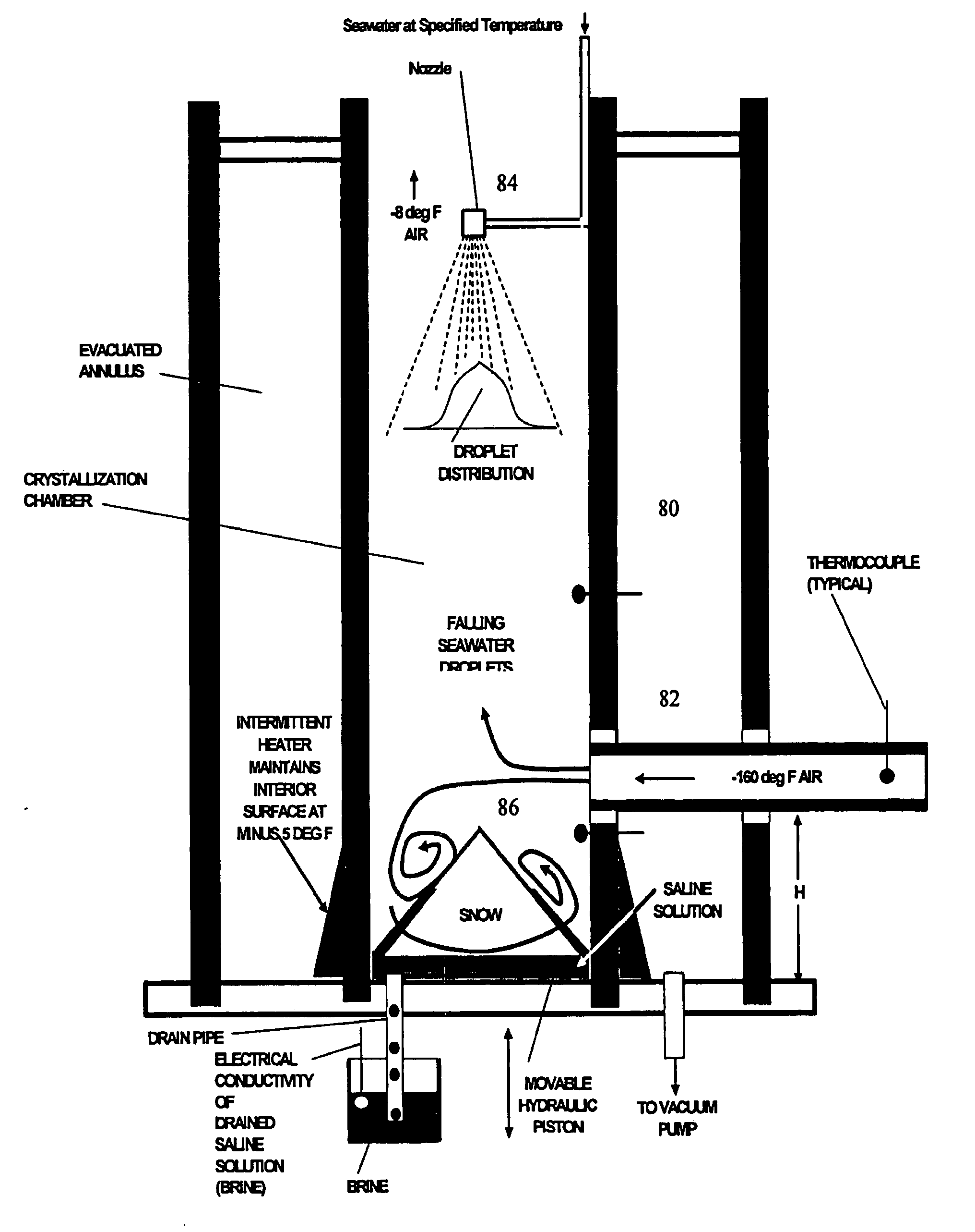
[0090]The freeze crystallization method of desalinating water discussed above requires a cooling system to freeze the seawater which is needed to separate the pure water from the impurities in the seawater. The present invention uniquely incorporates the use of compressed air energy technology as a means of co-producing chilled air as a by-product, wherein a turbo expander can be used to release and expand compressed air energy, to produce a suitable amount of chilled air for desalination purposes.

A. Compressed Air Energy Systems:

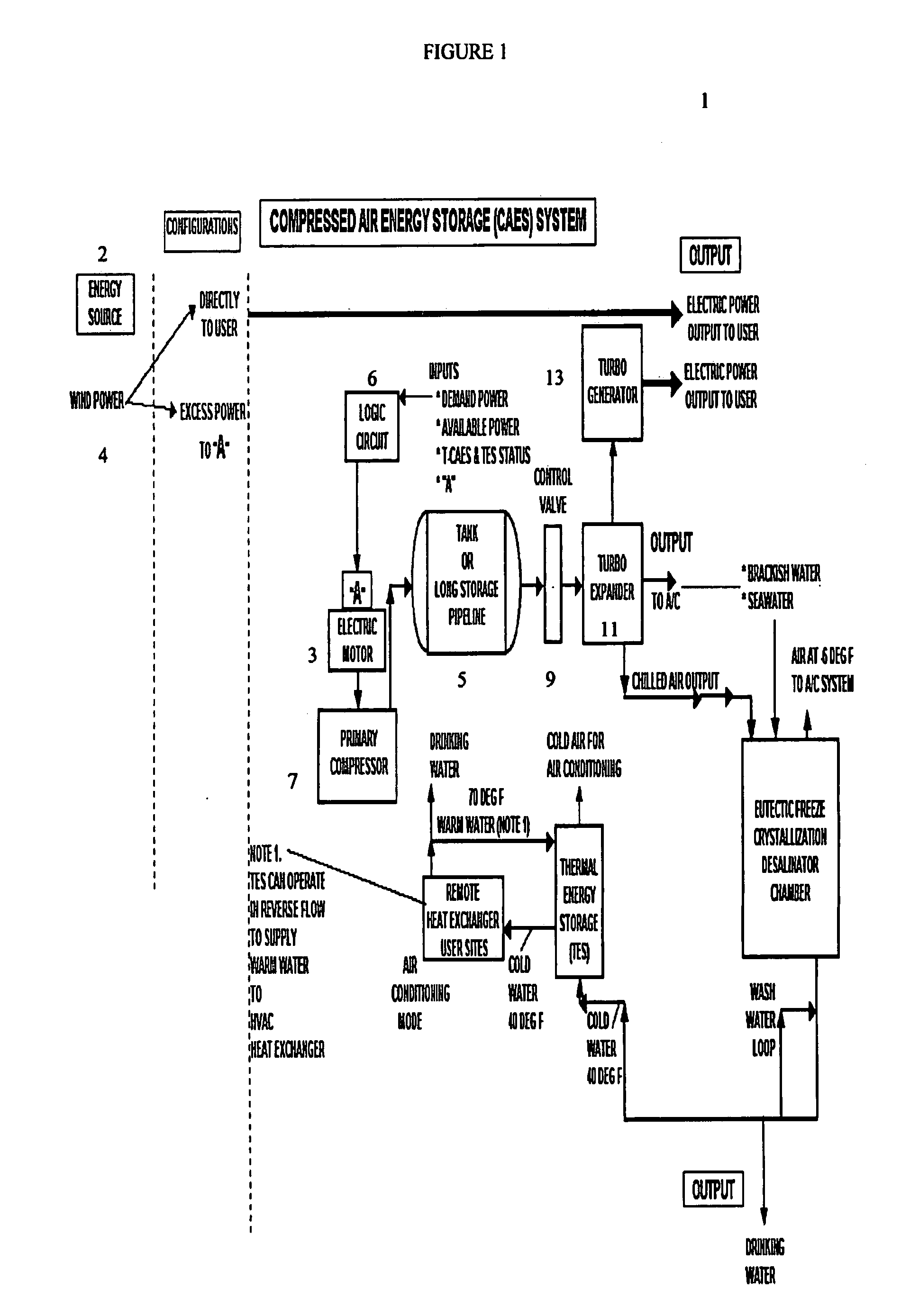
[0091]The present invention preferably contemplates using one of at least three different methods of producing chilled air, including (1) a compressed air energy storage system having a compressor and a large high pressure storage tank, wherein a turbo expander is used to release and expand the compressed air energy when it is needed, wherein the energy can be converted into chilled air and / or electrical energy, (2) a turbo expander having the dual capacity...


PUM

PropertyMeasurementUnit
timeaaaaaaaaaa
freezing pointaaaaaaaaaa

Abstract

The invention relates to a desalination method and system that uses freeze crystallization technology that incorporates the use of compressed air energy as the source for freezing temperatures. When compressed air is released by a turbo expander, chilled air is produced as a by-product, wherein the chilled air is introduced into a crystallization chamber. Also injected into the chamber is a spray cloud of seawater droplets, which has been pre-chilled by heat exchange with the cold chamber walls, and which is then circulated and exposed to the chilled air in the chamber. The sizes of the droplets can vary, but are preferably predetermined, along with the relative temperatures, flows and speeds of the spray and chilled air, such that when the droplets are circulated within the chilled air, and settle at the bottom of the chamber, they are deposited at slightly above the eutectic temperature. This way, the ice / snow mass that forms at the bottom of the chamber will consist of frozen ice crystals, and a residue of salt water brine, which can runoff from the mass, either from the sides, or through any voids or channels that may form within the mass.

Description

FIELD OF THE INVENTION[0001]The present invention relates to the field of desalination systems, and in particular, to a desalination system that uses compressed air energy that can be released and expanded to co-generate chilled air, which in turn, can be used to freeze water, and produce fresh drinking water.BACKGROUND OF THE INVENTION[0002]In the United States, where there is a broad range of climate zones, and an abundance of rain in many areas, there is typically an adequate supply of fresh drinking water available in most regions of the country. Even in areas where water supplies are scarce, efforts have been made to transport water from where it is available, to where it is needed. For example, a significant amount of water is currently being transported from the Colorado River, via the California Aqueduct, to heavily populated, but dry, regions of Southern California, so that sufficient water will be available, not only for drinking purposes, but also for agriculture and irri...

Claims


Application Information

Patent Timeline
Patent Type & Authority Applications(United States)
IPC IPC(8): C02F1/22F25D9/00F25B27/00F25D17/02
CPCB01D5/0027B01D7/00C02F2201/009C02F2103/08C02F2201/001C02F1/22Y02W10/37Y02A20/212Y02A20/124
Inventor ENIS, BEN M.LIEBERMAN, PAUL
Owner ENIS BEN M
Why Eureka
Try Eureka