Pipe pressure testing method and apparatus

a technology of pressure testing and pipe pressure, applied in the direction of fluid tightness measurement, screw threaded joints, instruments, etc., can solve the problems of inability to easily allow other uses, inability to clean out or inspect, and risk of fitting breaking or cracking the inflatable bladder, etc., to achieve easy field repair and high initial force

Active Publication Date: 2010-02-18
RELIANCE WORLDWIDE CORP
View PDF61 Cites 23 Cited by
  • Summary
  • Abstract
  • Description
  • Claims
  • Application Information

AI Technical Summary

Benefits of technology

[0017]A further useful aspect of the invention is that it uses a threaded rotational valve for initial pressure relief instead of one which relies on sliding friction and an interference fit. A sliding interference fit can be easily subject to sticking and jamming, and can require high initial forces to activate unless under continuous lubrication, which is not the case with a valve of the present design.
[0018]A still further useful aspect of the invention is that, in comparison to the narrow openings and crevices and sliding components of some other devices, it provides for open and easy access to the valve interior and the sealing surfaces. This applies to the fitting surfaces as well as to the components, such as the pressure testing fitting and the removable tubular stem valve. This is important for cleaning and maintenance of the device / invention, which is intended for multiple uses and which is subject to contamination by dirt and debris in the daily work environment.
[0019]Yet another useful aspect of the invention is that, in some embodiments, it can employ replaceable seal devices, such as planar o-rings, which are standard and readily available to the end user of the pressure testing devices for easy field repair if required.

Problems solved by technology

This is troublesome and there is thus a need for an easier way to block the line for testing.
But in some cases it may be desirable to fill at the test fitting and yet not release the test pressure by allowing to fluid flow through the pipe rather than venting at the test fitting.
But the inflatable bladders risk breaking or cracking the fitting by over-inflating the sealing bladder.
Most of these provide small openings in the pipe and are thus suited only for pressure testing but do not readily allow other uses, such as pipe cleanout or inspection.
But that design requires a large, complex shaped opening and a large, complex shaped seal that bends at right angles, neither of which are proven to stand the test of time and repeated use.
Moreover, the generally V-shaped notch extends to the midline of the pipe fitting and significantly weakens the fitting, causing deformation and leakage when the fitting is deformed by the weight of the adjoining pipeline.
As reflected by this patent, it is believed disadvantageous to form a pressure testing fitting in the same opening as a cleanout fitting, in part because many plumbing codes require that the cleanout fitting have an opening that is no smaller than 0.5 inches smaller than the nominal size of the pipe and such a large opening weakens the fitting and pipeline.

Method used


Image

  • Pipe pressure testing method and apparatus
  • Pipe pressure testing method and apparatus
  • Pipe pressure testing method and apparatus

Examples


Embodiment Construction

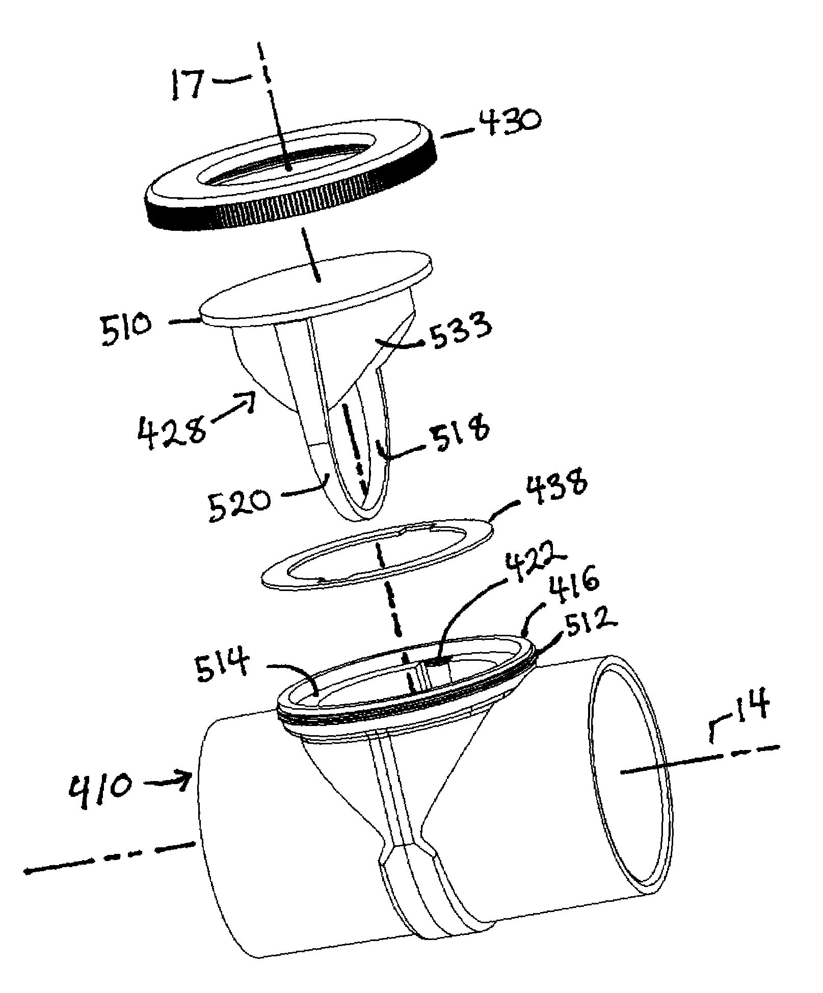
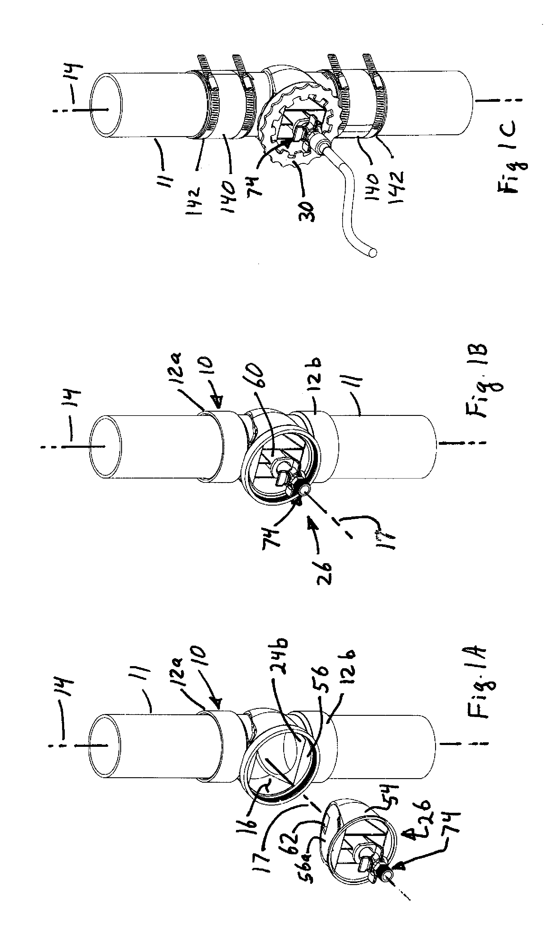
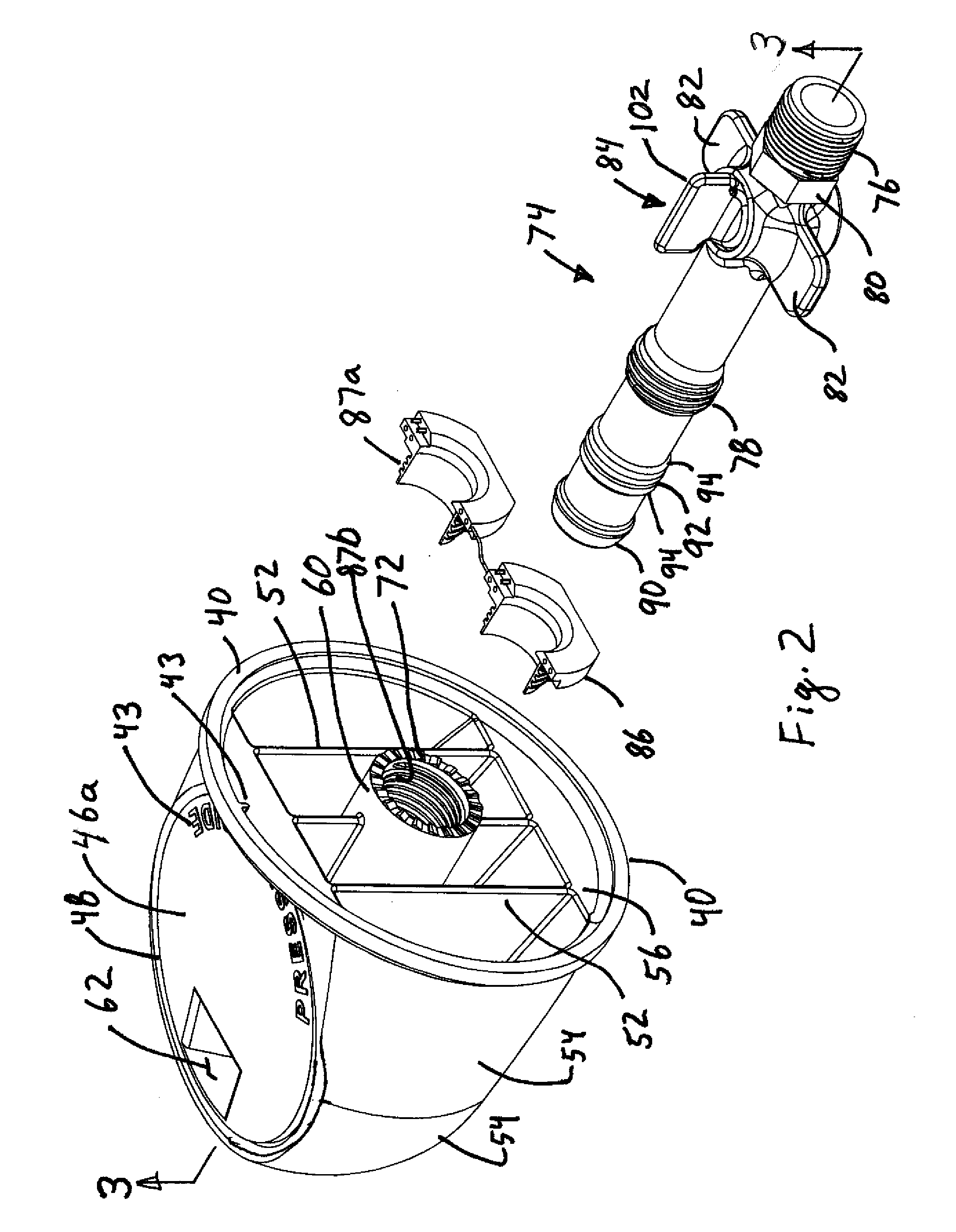
[0089]Referring to FIGS. 1-9, and especially FIGS. 1-4, the plumbing fitting 10 has at least one end, and preferably two opposing ends 12a, 12b, adapted to connect to an end of a pipe line or other conduit for pressure testing the line. The fitting 10 is advantageously made of a polymer, such as ABS or PVC plastic, although other materials could be used, including metal and cast iron. Typically the ends of the pipe line are inserted into mating ends of the fitting as shown in FIGS. 1A and 1B, although the fitting could abut the end(s) of the pipeline with flexible tubular seals clamped over abutting ends of the fitting 10 and pipeline 11 with hose clamps in order to hold the parts in alignment and to ensure the fluid seal as shown in FIG. 1C.

[0090]The fitting 10 has a longitudinal axis 14 along which fluid flows. The fitting has as opening or port 16 into which an apparatus is inserted to regulate flow through the fitting. The fitting has exterior walls 18 and interior walls 20. A f...


PUM


Abstract

A pipeline pressure testing assembly has a fitting defining a flow path and having a port on a wall of the fitting into which a pressure testing device is removably inserted along a central axis of the port for pressure testing. The port is circular, larger than the interior diameter of the pipeline and located at or above the tube forming the flow path through the fitting. The fitting has a recess encircling at least part of the flow path and opening to the port to receive the testing and sealing devices. The recess is formed by two opposing walls inclined relative to the central axis of the recess. The recess walls at the top of the flow path by the port are spaced apart a distance as large as the pipe diameter for cleanout and inspection. A tubular valve stem screws into the testing device and has a rotary valve blocking flow through the tubular valve stem. Flow through the fitting is blocked with the rotary valve closed and the tubular valve stem in a first position. Flow through the testing device is allowed with the rotary valve closed and the tubular valve stem in an open position. With the rotary valve open, flow through the tubular valve stem is permitted when the tubular valve stem is in either the first or second position to provide multiple drain and fill options.

Description

CROSS-REFERENCE TO RELATED APPLICATIONS[0001]The application claims the benefit under 35 U.S.C. §119(e), of application Ser. No. 60 / 089,360, filed Aug. 15, 2008, the entire contents of which are incorporated herein by reference.BACKGROUNDBackground of the Invention[0002]Buildings and houses have pipe lines that need to be pressure tested in order to verify that the various joints in the pipe line do not leak. Such lines include water lines and drainage lines. This testing is typically done by hooking up a source of pressurized air or water to the line and filling the line. Because an open line will not hold the pressure for testing, the end(s) of each line or segments of the line must be capped or plugged prior to introducing the pressurized air or water. This is troublesome and there is thus a need for an easier way to block the line for testing.[0003]Further the line must frequently be tested in an intact state, after all joints have been fully assembled. If a single joint or a se...

Claims


Application Information

Patent Timeline
Patent Type & Authority Applications(United States)
IPC IPC(8): G01M3/28F16J15/16
CPCG01M3/022G01M3/2815G01M3/2853G01M3/04F16L15/04
Inventor HART, DENNIS L.GONZALEZ, CRISTOBALO'NEIL, VIRGIL E.JARAMILLO, JEFFREY A.BROWN, LARRY D.
Owner RELIANCE WORLDWIDE CORP
Why Eureka
Try Eureka