Joined concentric tubes

a technology of concentric tubes and joints, applied in the direction of cell components, sustainable manufacturing/processing, final product manufacturing, etc., can solve the problem of inability to meet the requirements of tubular production, and achieve the effect of facilitating tubular production and facilitating joining

Active Publication Date: 2010-02-18
RGT UNIV OF CALIFORNIA
View PDF99 Cites 32 Cited by
  • Summary
  • Abstract
  • Description
  • Claims
  • Application Information

AI Technical Summary

Benefits of technology

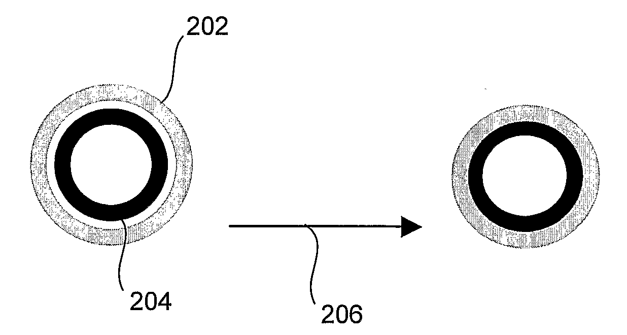
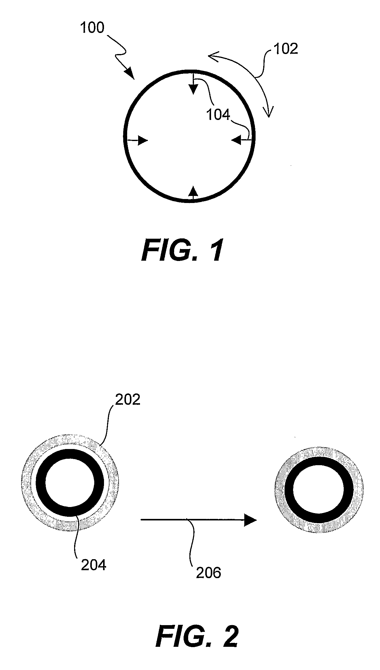
[0010]The invention facilitates the manufacture of tubular objects having two or more concentric layers that have different properties. The layers are joined to one another during their manufacture primarily by compressive and friction forces and possibly mechanical interlocking; it is not necessary for the concentric tubes to display adhesive-, chemical- or sinter-bonding to each other in order to achieve a strong bond. This facilitates

Problems solved by technology

This is not possible in a manufacturing scheme where all of the laye

Method used


Image

  • Joined concentric tubes
  • Joined concentric tubes
  • Joined concentric tubes

Examples


example

[0053]The following example is provided to illustrate and provide structural and performance details for a specific embodiment of the present invention. The example is provided to exemplify and more clearly illustrate aspects of the present invention and is in no way intended to be limiting.

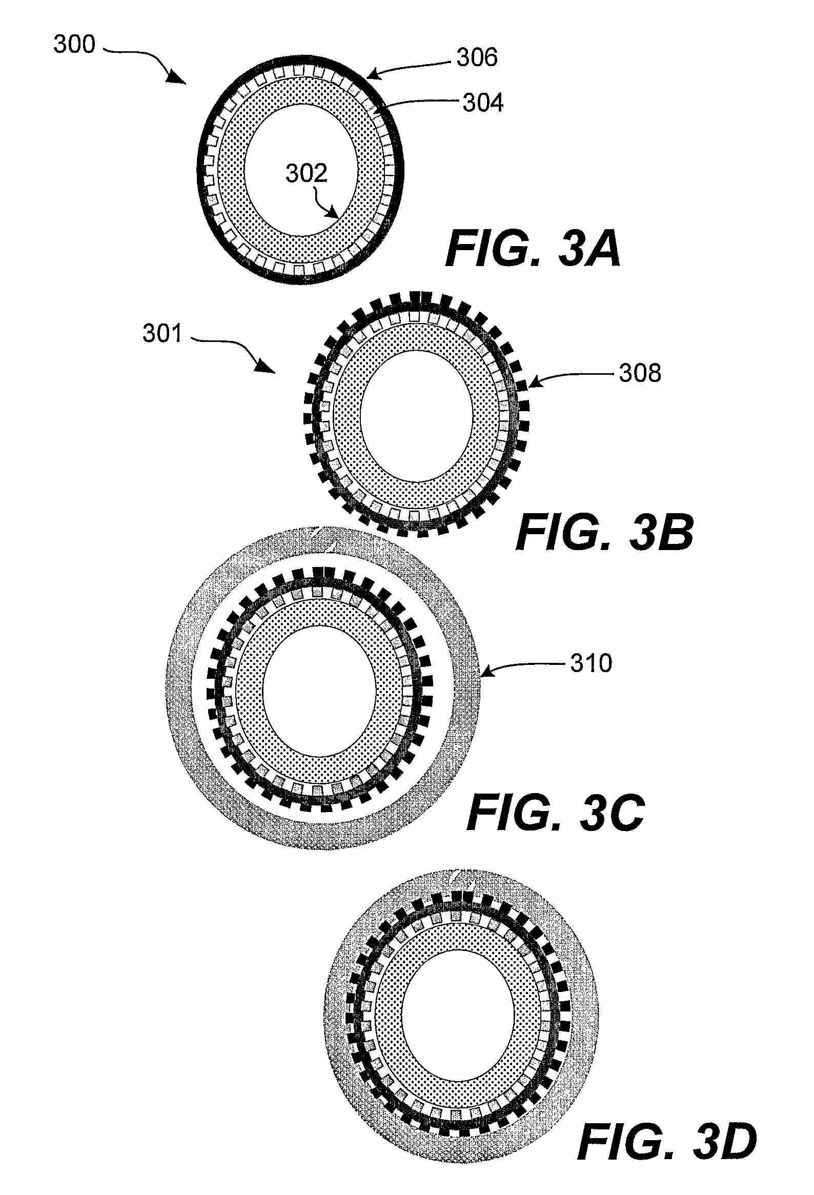
[0054]The method for achieving the structure presented in FIG. 4 will be described. In this case, the internal tube comprised a porous metal support layer (internal CC), internal electrode, and dense YSZ electrolyte. The external electrode was applied as a paint to the internal tube before inserting the internal tube into the external tube. The paint consisted of YSZ powder, aqueous acrylic binder, and polymethyl methacrylate pore former particles. The external tube (external CC) was debinded, bisque fired, and slipped around the internal tube prior to sintering the two tubes together. During sintering, the intimate contact between the external electrode and external CC that is evident in FIG. 4 ...


PUM

PropertyMeasurementUnit
Particle sizeaaaaaaaaaa
Fractionaaaaaaaaaa
Lengthaaaaaaaaaa

Abstract

Tubular objects having two or more concentric layers that have different properties are joined to one another during their manufacture primarily by compressive and friction forces generated by shrinkage during sintering and possibly mechanical interlocking. It is not necessary for the concentric tubes to display adhesive-, chemical- or sinter-bonding to each other in order to achieve a strong bond. This facilitates joining of dissimilar materials, such as ceramics and metals.

Description

STATEMENT OF GOVERNMENT SUPPORT[0001]This invention was made with government support under Contract DE-AC02-05CH11231 awarded by the United States Department of Energy to The Regents of the University of California for the management and operation of the Lawrence Berkeley National Laboratory. The government has certain rights in this invention.FIELD OF THE INVENTION[0002]The present invention relates to the joining of concentrically disposed tubular objects and has important applications in high-temperature electrochemical devices, such as solid oxide fuel cells. The invention is relevant to any situation where tubular objects are produced by a method in which one tube shrinks radially on another upon sintering during manufacture, and the resulting object has properties that vary in the radial direction.BACKGROUND[0003]Solid-state electrochemical devices are normally cells that include two porous electrodes, the anode and the cathode, and a dense solid electrolyte membrane disposed ...

Claims


Application Information

Patent Timeline
IPC IPC(8): B29C65/02F16L9/14
CPCB22F5/106B22F7/004B22F7/062H01M8/004H01M8/0252Y02E60/525H01M8/1213H01M8/243H01M2008/1293Y02E60/521H01M8/0297Y02P70/50Y02E60/50
Inventor TUCKER, MICHAEL C.JACOBSON, CRAIG P.VISCO, STEVEN J.DE JONGHE, LUTGARD C.
Owner RGT UNIV OF CALIFORNIA
Why Eureka
Try Eureka