
Thermal Effect Measurement with Mid-Infrared Spectroscopy

a technology of thermal effect and infrared spectroscopy, which is applied in the direction of optical radiation measurement, instruments, and investigating composite materials, can solve the problems of affecting the thermal effect of composite materials, and affecting the color of the composite material or the surface film, etc., and achieves the effect of increasing the thermal exposur

Active Publication Date: 2010-02-18
THE BOEING CO
View PDF29 Cites 10 Cited by
  • Summary
  • Abstract
  • Description
  • Claims
  • Application Information

AI Technical Summary

Benefits of technology

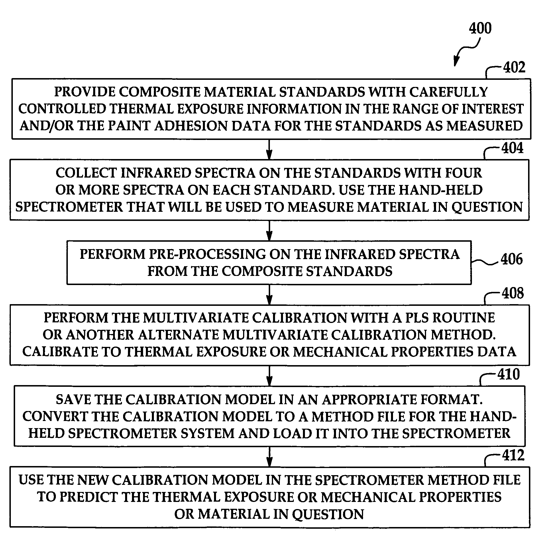
[0009]The disclosure is further generally directed to a method of determining a physical property of a composite material. An illustrative embodiment of the method includes providing a series of composite material standards with increasing thermal exposure (with or without a surfacing film), irradiating the composite material standards and / or the surfacing films with mid-spectrum infrared energy, detecting infrared energy reflected from the composite material standards / surfacing films, performing multivariate calibration on the series of the infrared spectra reflected from the composite material standards / surfacing films, performing a multivariate calibration to the infrared spectra from the standards to make a model of the spectral changes with increasing thermal exposure (or decreasing mechanical properties), and using the multivariate model to predict the thermal exposure or mechanical properties of composite materials in question.

Problems solved by technology

Structures which are constructed of resin-fiber composite materials may be exposed to heat, which may affect the composite materials in various ways.
These repairs may require the use of heating blankets that are notorious for having hot spots.
Thus, during the repair some areas of the composite material or surfacing film may become overheated; in the case of epoxy-based surfacing films, a color change (dark or blackened) may be noticeable.
Thermal effect for in-service airplanes can occur from engine and run-way fires, electrical problems, lightening strikes, and other causes.
Thermal effect may affect the mechanical and structural integrity of composite materials and surfacing films.
Furthermore, thermal effect to composite materials or surfacing films may not follow a linear course.

Method used


Image

  • Thermal Effect Measurement with Mid-Infrared Spectroscopy
  • Thermal Effect Measurement with Mid-Infrared Spectroscopy
  • Thermal Effect Measurement with Mid-Infrared Spectroscopy

Examples


Embodiment Construction

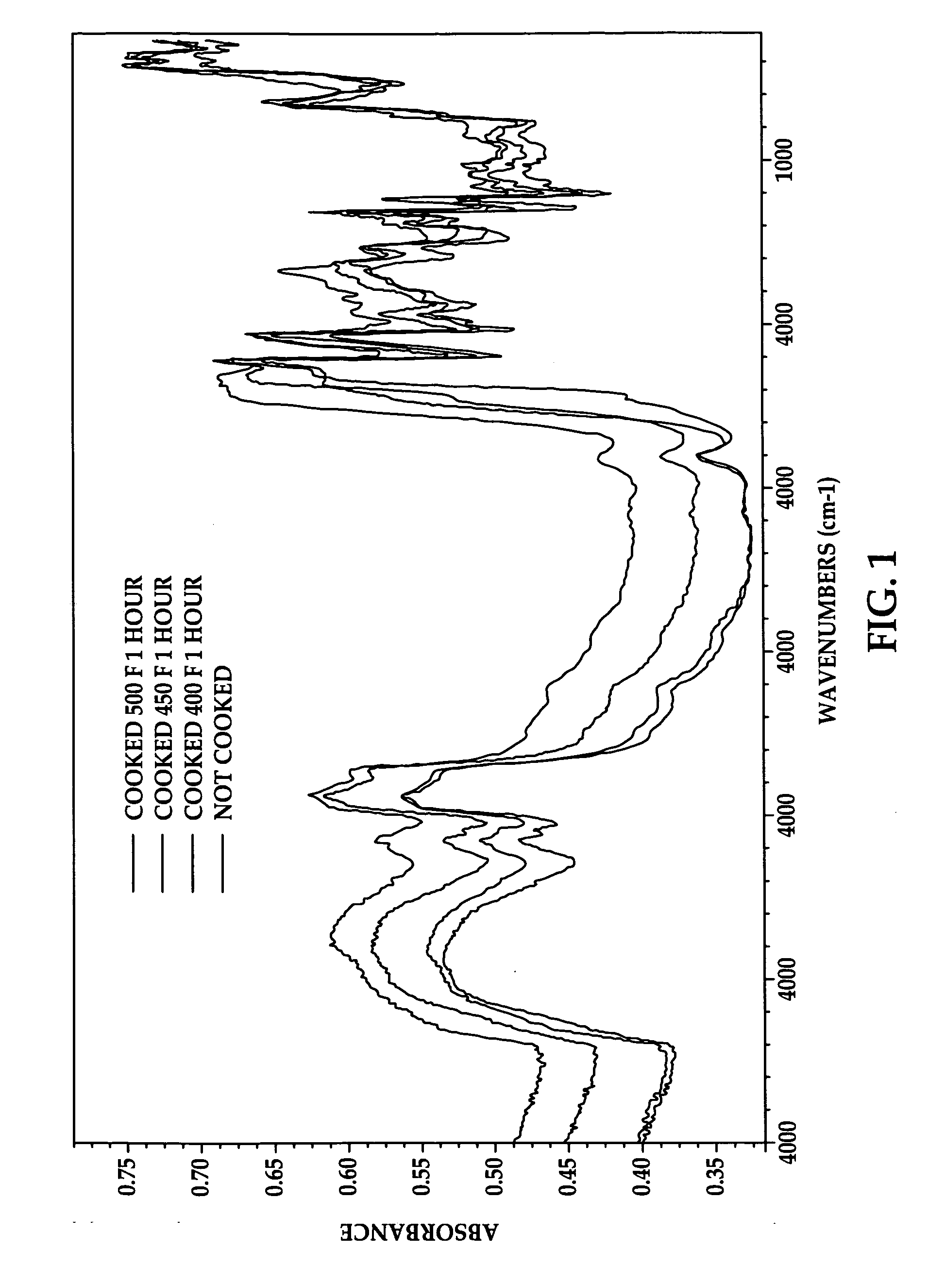
[0010]FIG. 1 is a series of mid-IR spectra on thermally exposed graphite composite (CFRP) standards which were exposed for 1 hour each at 400, 450 and 500° F. and no thermal exposure, respectively.

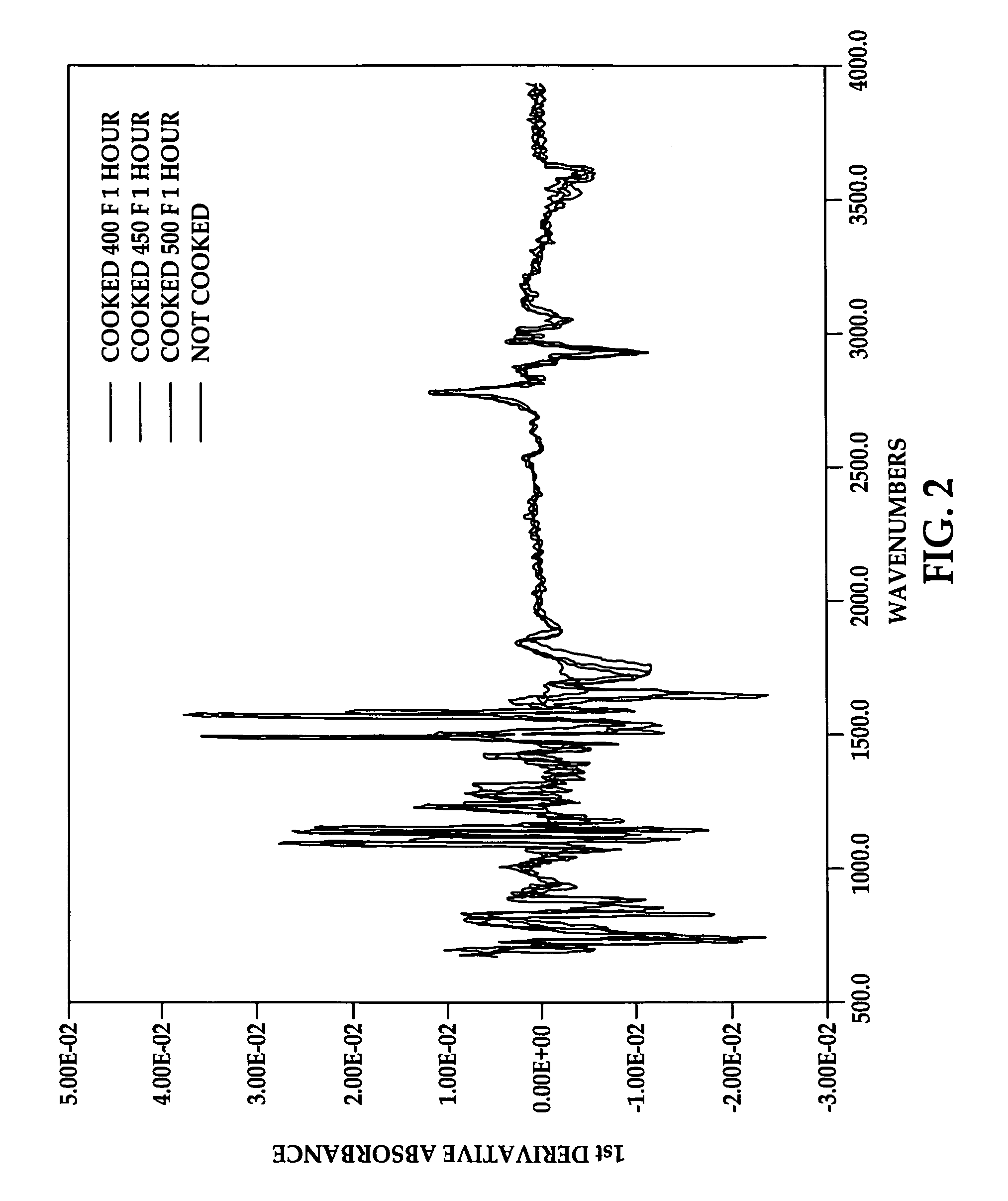
[0011]FIG. 2 is a the same series of mid-IR spectra from FIG. 1 but with first derivative and 7 point smoothing pre-processing with the Savitzky Golay method.

[0012]FIG. 3 is the regression vector from the multivariate calibration of the mid-IR spectra to the un-notched compression test stress results of the standards using the PLS (partial least squares) multivariate calibration method.

[0013]FIG. 4 is a flow diagram which illustrates the multivariate calibration and prediction method.

[0014]FIG. 4A is a flow diagram which illustrates important points in the multivariate calibration method.

[0015]FIG. 5 is a flow diagram of an aircraft production and service methodology.

[0016]FIG. 6 is a block diagram of an aircraft.

DETAILED DESCRIPTION OF THE PREFERRED EMBODIMENT

[0017]Referring initially to ...


PUM

PropertyMeasurementUnit
mid-IR wavelength rangeaaaaaaaaaa
physical propertiesaaaaaaaaaa
infrared spectraaaaaaaaaaa

Abstract

A method of determining a physical property of a composite material includes providing a series of composite materials / surfacing films, which are subjected to increasing thermal experience to create a set of thermal effect standards, collecting mid-IR spectra on those standards, performing data pre-processing and then multivariate calibration on the spectra of the composite materials / surfacing films, and using that calibration to predict the thermal effect for samples in question.

Description

CROSS REFERENCE TO RELATED APPLICATIONS[0001]This application is related to co-pending U.S. patent application Ser. No. ______, (Attorney Docket No. 08-0107) Ser. No. ______ and (Attorney Docket No. 08-0084); and Ser. No. ______, (Attorney Docket No. 08-0091); and Ser. No. ______, (Attorney Docket No. 08-0092) all filed concurrently herewith on Jun. 28, 2008, each of which applications is incorporated by reference herein in its entirety.FIELD OF THE INVENTION[0002]The disclosure relates to methods for determining thermal effect in composite materials. More particularly, the disclosure relates to a method for accurately assessing thermal effect in a composite material or surfacing film using mid-infrared spectroscopy.BACKGROUND OF THE INVENTION[0003]Resin-fiber composite materials are utilized in a variety of applications including the aerospace industry, for example. Structures which are constructed of resin-fiber composite materials may be exposed to heat, which may affect the comp...

Claims


Application Information

Patent Timeline
Patent Type & Authority Applications(United States)
IPC IPC(8): G01N21/35
CPCG01N21/3563G01N2201/129G01N2201/0221G01N2021/8472
Inventor SHELLEY, PAUL H.WERNER, GREGORY J.VAHEY, PAUL G.
Owner THE BOEING CO
Learn More