Calibration of ultrasonic elasticity-based lesion-border mapping

a technology of elasticity and calibration, applied in the field of mapping calibration and/or lesion border detection, can solve the problems of low signal-to-noise ratio (s/n), low spatial resolution of low frequency imaging, and insufficient sensitive ultrasound-based elastography measurements to accurately detect the boundary portion of ablated tissue in the vicinity of a stiff medical instrument. , to achieve the effect of increasing thermal exposure, and reducing the risk of ablation

Active Publication Date: 2018-06-21
KONINKLJIJKE PHILIPS NV
View PDF3 Cites 23 Cited by
  • Summary
  • Abstract
  • Description
  • Claims
  • Application Information

AI Technical Summary

Benefits of technology

[0008]Because of tremendous changes in the elasticity of temperature-elevated tissue, ultrasound elasticity imaging has great potential in ablation monitoring. As the tissue necrosis threshold is reached, the tissue begins to harden and continues to do so with increased thermal exposure. By tracking this change, the therapy progress can be evaluated and the end point can be determined. Tissue stiffness can be measured using shear wave imaging. This entails the use of acoustic radiation force to generate displacement and shear waves that are then tracked to extract stiffness information. Shear waves travel faster with lower displacement in stiffer body tissue.

Problems solved by technology

However, known SWI modes employed in ultrasound-based elastography are not sufficiently sensitive to accurately detect an ablated tissue boundary portion in the vicinity of a stiff medical instrument, such as an ablation needle or tine extending from the needle's electrode.
Firstly, the rigidity of the instrument restricts shear wave displacement of the ablated tissue surrounding the needle.
Secondly, the measurements of elasticity, e.g., shear modulus, suffer from low signal-to-noise (S / N) ratio.
The low frequency imaging suffers from low spatial resolution, but higher frequencies are limited as to imaging depth penetration.
The limitation is especially severe for the ablation of a lesion of more than 40 millimeters (mm) in depth and less than 15 mm in diameter, located near a critical structure (e.g., a nerve or blood vessel) that needs to be protected from ablation.
Also it would be difficult to delineate the expanding thermal lesion boundary with respect to the initial tumor contour.
Some of the hurdles to efficient elasticity assessment in shear modulus-based real-time monitoring of ablation are as follows: (1) it is hard to determine where is the peak of very low-displacement shear wave, (2) it is also hard to differentiate the peaks of a very fast shear wave between two neighboring points; (3) there exists even less displacement for the ablated tissue when the ablation needle is present during ablation; and (4) reflection of shear wave from the ablation needle complicates the shear wave profiles with more than one peak.

Method used


Image

  • Calibration of ultrasonic elasticity-based lesion-border mapping
  • Calibration of ultrasonic elasticity-based lesion-border mapping
  • Calibration of ultrasonic elasticity-based lesion-border mapping

Examples


Embodiment Construction

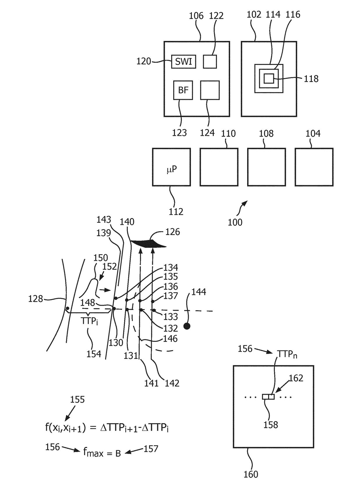
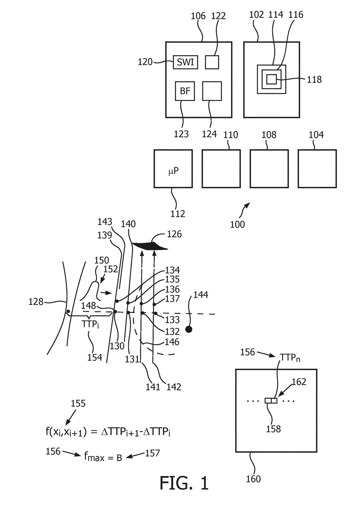
[0026]FIG. 1 depicts, by way of illustrative and non-limitative example, a real-time, thermal ablation monitoring elastography apparatus 100. The apparatus 100 includes an ablation device 102, an energy source 104, an imaging device 106, a display 108, user controls 110, and a microprocessor 112 or other processor such as a shear wave elastography computing unit. The microprocessor function is realizable in one or more integrated circuits. However, it could be implemented with any combination of software, firmware, and hardware.

[0027]The ablation device 102 includes, as a type of ablation equipment, an ablation needle 114. The latter includes radiofrequency (RF) electrode 116 which includes one or more tines 118 extendable into body tissue to apply heat for ablation. The energy source 104, such as the mains electrical current, provides energy for the heating. The ablation needle 114 may instead be one used for cryotherapy or microwave ablation, with an alternative corresponding cons...


PUM


Abstract

A medium of interest is interrogated according to ultrasound elastography imaging. A preliminary elasticity-spatial-map is formed. This map is calibrated against a reference elasticity-spatial-map that comprises an array (232) of different (240) elasticity values. The reference map is formed to be reflective of ultrasonic shear wave imaging of a reference medium. The reference medium is not, nor located at, the medium of interest, and may be homogeneous. Shear waves that are propagating in a medium are tracked by interrogating the medium. From tracking locations on opposite sides of an ablated-tissue border, propagation delay of a shear wave in the medium and of another shear wave are measured. The two shear waves result from respectively different pushes (128) that are separately issued. A processor decides, based on a function of the two delays, that the border crosses between the two locations. The calibrated map is dynamically updated and may include post-ablation border expansion (346) and time-annotated previous stages (344, 348).

Description

[0001]The present invention claims priority to U.S. Prov. Appl. No. 62 / 140672, filed on Mar. 31, 2015, which is herein incorporated by reference in its entirety.FIELD OF THE INVENTION[0002]The present invention relates to using imaging for spatial mapping of elasticity and, more particularly, to map calibration and / or lesion border detection.BACKGROUND OF THE INVENTION[0003]Thermal ablation techniques, as alternatives to major surgery, are minimally invasive requiring only needles (radio-frequency (RF), cryotherapy, and microwave ablation) or non-invasive heat source such as using high-intensity focused ultrasound (HIFU). In most of the procedures, the cancerous tissue is heated to above 55° C. and coagulated.[0004]RF ablation (RFA) is currently the only FDA approved thermal ablation therapy in the United States. It uses a probe with an active electrode tip through which a 460-500 kHz alternating electric current is conducted. The current causes ionic agitation and frictional heatin...

Claims


Application Information

Patent Timeline
Patent Type & Authority Applications(United States)
IPC IPC(8): A61B8/08A61B18/14A61N7/02A61B8/00
CPCA61B8/485A61B8/085A61B18/1477A61N7/02A61B8/5223A61B8/587A61B2017/00106A61B2018/00577A61B2018/0212A61B2018/1869A61N2007/0052A61B18/12
Inventor SHI, WILLIAMANAND, AJAYHUANG, SHENG-WENSETHURAMAN, SHRIRAMXIE, HUA
Owner KONINKLJIJKE PHILIPS NV
Why Eureka
Try Eureka