Wind energy system with fluid-working machine with non-symmetric actuation

a fluid working machine and wind energy technology, applied in the direction of wind energy generation, reciprocating piston engines, fluid gearings, etc., can solve the problems of many and strict requirements for the transmission box, the failure of many wind turbine gearboxes, and the difficulty of correct dimensioning of the gearbox with regard to the load spectrum

Active Publication Date: 2010-02-18
GENERAL ELECTRIC CO
View PDF3 Cites 162 Cited by
  • Summary
  • Abstract
  • Description
  • Claims
  • Application Information

AI Technical Summary

Benefits of technology

[0013]Further aspects, advantages and features of the present invention are apparent from the dependent claims, the description and the accompanying drawings.

Problems solved by technology

For large wind energy systems, a transmission box is inevitable in the majority of cases as a result of the high loads that arise from the energy entered from the rotor.
However, the construction of the transmission box causes problems as many load changes take place due to the fact that the energy from the wind frequently varies.
Therefore, the requirements for the transmission box are numerous and strict.
In the early phase of wind energy systems, the gearbox was the source of failures and defects in many wind turbines.
The reason for these gearbox problems was the difficulty of a correct dimensioning of the gearbox with regard to the load spectrum.
Today, the early phase problems have been largely solved, but the construction of the gearboxes is still a difficult task considering size, mass and costs.

Method used


Image

  • Wind energy system with fluid-working machine with non-symmetric actuation
  • Wind energy system with fluid-working machine with non-symmetric actuation
  • Wind energy system with fluid-working machine with non-symmetric actuation

Examples


Embodiment Construction

[0028]Reference will now be made in detail to the various embodiments of the invention, one or more examples of which are illustrated in the figures. Each example is provided by way of explanation of the invention, and is not meant as a limitation of the invention. For example, features illustrated or described as part of one embodiment can be used on or in conjunction with other embodiments to yield yet a further embodiment. It is intended that the present invention includes such modifications and variations.

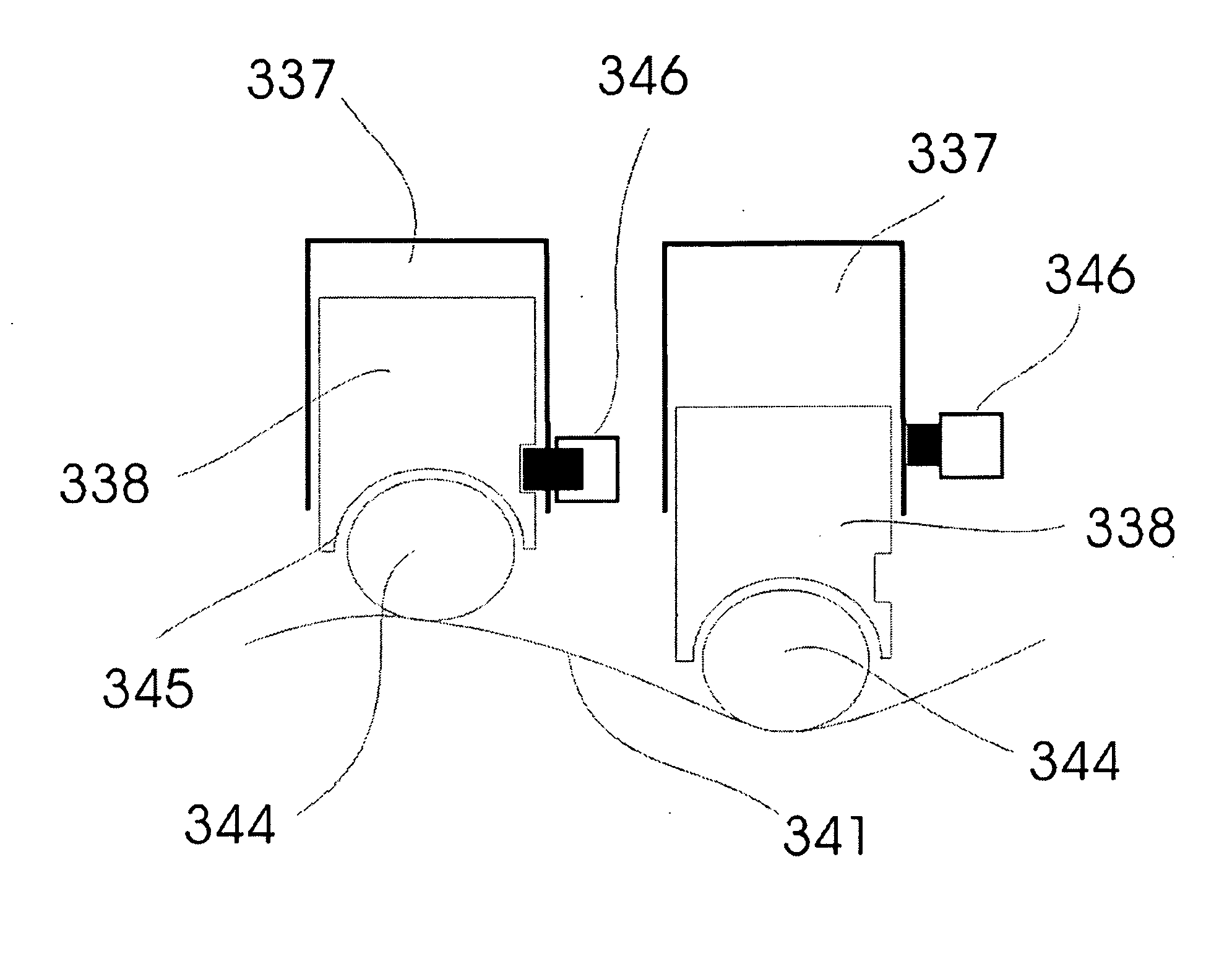
[0029]Generally, embodiments described herein refer to a fluid-working machine with non-symmetric actuation acting as a transmission. A fluid-working machine allows the hydraulic energy transmission. For fluid working machines, different actuation principles are known, such as radial piston machines actuated by an eccentricity or axial piston machines actuated by a pivoted eccentric disc or camshaft. Thereby a continuously variable transmission of the rotor torque to the genera...


PUM


Abstract

The invention relates to a wind energy system with hydraulic energy transmission with non-symmetric actuation. The non-symmetric actuation is caused by valve control and mechanical means for controlling the actuation of the pistons. A cylinder unit is provided comprising a drive unit and an output unit associated with two hydraulic connections. The drive and the output unit comprise a minimum of two cylinders, in which pistons are reciprocating. Some of the cylinders can be switched off during low wind speeds. The cylinders communicate with a low pressure manifold and a high pressure manifold. These manifolds are part of the hydraulic connections. Use of the fluid-working machine as transmission in wind energy systems increases the overall economical efficiency.

Description

BACKGROUND OF THE INVENTION[0001]The present invention relates to wind energy systems and fluid working machines. Specifically, the present invention relates to a wind energy system with a fluid working machine acting as a transmission.[0002]Wind energy systems are experiencing an increasing demand. Therefore, large multi-megawatt wind turbines are being installed in many locations throughout the world. They change the kinetic energy of the wind to electrical energy. For large wind energy systems, a transmission box is inevitable in the majority of cases as a result of the high loads that arise from the energy entered from the rotor. However, the construction of the transmission box causes problems as many load changes take place due to the fact that the energy from the wind frequently varies. Therefore, the requirements for the transmission box are numerous and strict.[0003]It is known in the art to use a gearbox as transmission box. In the early phase of wind energy systems, the g...

Claims


Application Information

Patent Timeline
Patent Type & Authority Applications(United States)
IPC IPC(8): F03D11/02F03D9/00
CPCF03D9/001F03D11/02F05B2260/406Y02E10/722F16H39/20F16H61/444F16H39/18F03D15/00F03D9/28F03D9/25F03D15/20Y02E10/72
Inventor NIES, JACOB JOHANNESHEMMELMANN, JAN ERICH
Owner GENERAL ELECTRIC CO
Why Eureka
Try Eureka