
Total aortic arch reconstruction graft

a total aortic arch and graft technology, applied in the field of vascular grafts, can solve the problems of difficult exposure of the descending aorta, difficult to expose the descending aorta, and significant challenge in the cardiac surgeon's replacement of the entire aortic arch

Active Publication Date: 2010-02-18
SHERIF HISHAM M F
View PDF26 Cites 16 Cited by
  • Summary
  • Abstract
  • Description
  • Claims
  • Application Information

AI Technical Summary

Benefits of technology

[0019]an initial diameter of said second end of the secon...

Problems solved by technology

Replacement of the entire aortic arch presents a significant challenge to the cardiac surgeon.
Exposure of the descending aorta is much more difficult than exposure of the ascending aorta, which is itself difficult to expose.
However, bleeding from the suture line where the graft has been attached to the descending aorta is a common problem.
The need to control bleeding often requires maintaining the patient on deep hypothermic arrest for a longer period of time, which increases the risk of neurologic and other organ injury.
This graft relies upon its stent section to fix itself against the descending aortic wall, and can suffer from the problem of bleeding from the suture line where the graft is attached to the descending aorta.
The collar functions as a sewing ring, and must be trimmed to fit the patient's aorta, which undesirably increases the duration of deep hypothermic arrest.
Secure placement of the junction between the two graft segments at the open end of the descending aorta is difficult due to the discrepancy between the trimmed collar's diameter and that of the graft.
Moreover, conventional sutures must be used to attach this graft, which increases the probability the suture line will bleed.

Method used


Image

  • Total aortic arch reconstruction graft
  • Total aortic arch reconstruction graft

Examples


Embodiment Construction

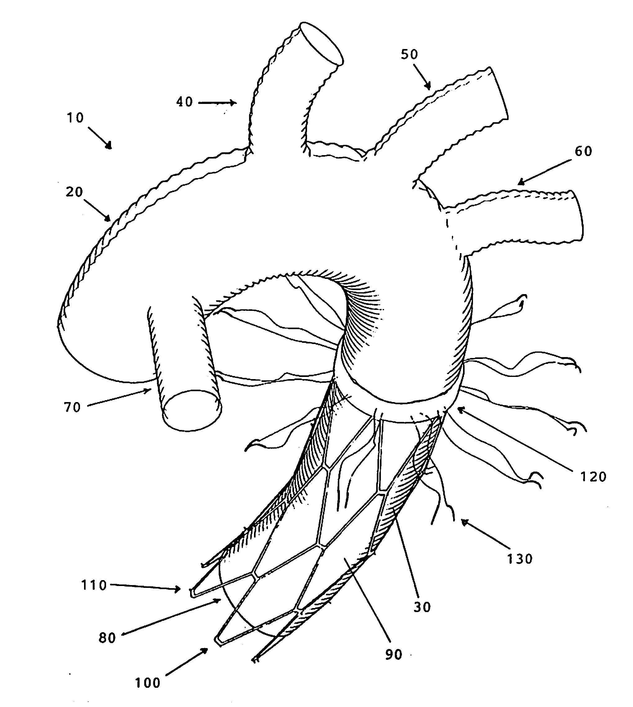
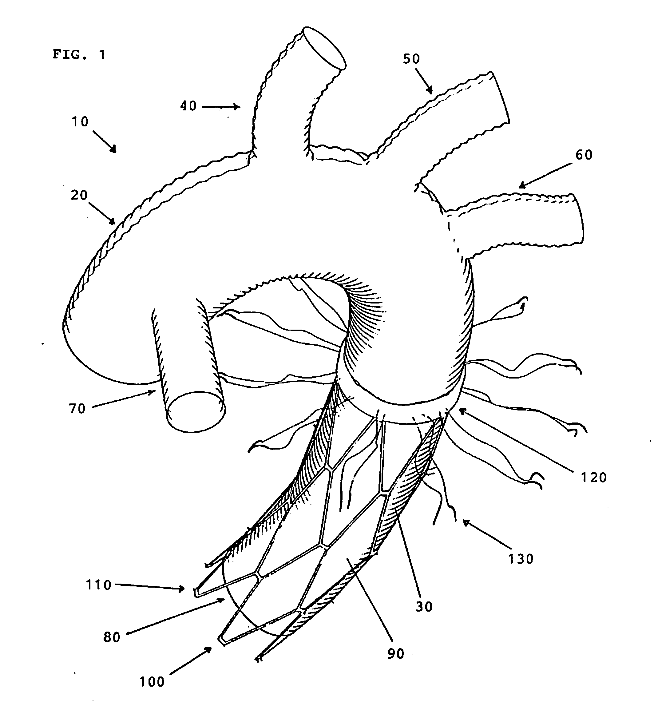
[0022]The inventor has discovered the aorta may be more easily and quickly replaced using a reconstruction graft comprising

[0023]a) a first, hollow cylindrical segment in the shape of an aortic arch and having two opposed ends and a pre-determined diameter,[0024]said first segment having three hollow cylindrical side branches in communication therewith, said three side branches in the same or substantially the same plane with one another and adapted to be joined to a patient's left subclavian artery, left common carotid artery and innominate artery, respectively,[0025]said first segment having a fourth hollow cylindrical side branch adapted to be joined to a perfusion device;[0026]a first end of said first segment being adapted to be joined to the ascending aortic wall of a patient;

[0027]b) a second, hollow cylindrical segment having two opposed ends,[0028]a first end of said second segment being joined to the second end of said first segment,[0029]a second end of said second segmen...


PUM


Abstract

A total aortic arch reconstruction graft, includinga) a first, hollow cylindrical segment in the shape of an aortic arch and adapted to be joined to a patient's ascending aorta, and including three side hollow cylindrical branches in communication therewith and adapted to be joined to a patient's left subclavian artery, left common carotid artery and innominate artery, respectively, and a fourth hollow cylindrical branch adapted to be joined to a heart-lung machine;b) a second, hollow cylindrical segment having a first end being joined to the second end of the first segment, and a second end adapted to be inserted into the descending aorta of a patient, the second segment having an expandable outer wall covered with an expandable open-mesh stent having means for attaching the second segment to an internal surface of a patient's descending aorta,c) a collar having a diameter slightly larger than the diameter of said first segment, the collar located at a juncture where the first end of the second segment is joined to the second end of the first segment, with the collar having means for attachment to the open end of a patient's descending aorta. A surgical procedure for total replacement of the aortic arch of a patient is also disclosed.

Description

[0001]This application claims the benefit of U.S. provisional application No. 61 / 189,226, filed Aug. 18, 2008, whose disclosure is incorporated by reference herein in its entirety.BACKGROUND OF THE INVENTION[0002]The present invention relates to vascular grafts. More particularly, this invention relates to a graft suitable for replacement of the entire aortic arch.[0003]Replacement of the entire aortic arch presents a significant challenge to the cardiac surgeon. Exposure of the descending aorta is much more difficult than exposure of the ascending aorta, which is itself difficult to expose. Accordingly, the vast majority of aortic surgical techniques call for inserting a folded graft inside the descending aorta by suturing the edge of the folded graft first to the rim (cut edge) of the descending aorta, then inverting the graft to straighten it and let it fall within the descending aorta, followed by expanding and fixing the graft against the descending aortic inner wall.[0004]The ...

Claims


Application Information

Patent Timeline
IPC IPC(8): A61F2/06A61B17/04
CPCA61F2/06A61F2/07A61F2/90A61F2002/8483A61F2002/8486A61F2002/075
Inventor SHERIF, HISHAM M. F.
Owner SHERIF HISHAM M F
Learn More