
Method for controlling a fuel injector of a diesel engine

a technology of fuel injector and diesel engine, which is applied in the direction of electrical control, process and machine control, etc., can solve the problems of negative effect of diesel engine operating response and increased ignition delay, and achieve the effects of improving engine operation efficiency, and improving smoothness of operation

Inactive Publication Date: 2010-02-18
ROBERT BOSCH GMBH
View PDF15 Cites 5 Cited by
  • Summary
  • Abstract
  • Description
  • Claims
  • Application Information

AI Technical Summary

Benefits of technology

The patent text describes a method for estimating the ignition delay in diesel engines and controlling it to improve engine performance. By using a computing model that processes performance parameters, the method provides an approximation of the actual value of combustion start. This allows for smoother operation and more efficient engine operation in a broad range of operating states and transitions between operating states. The method can also be combined with regulation of the combustion start to better control the combustion start even in steady-state operating states. The method takes into account the influence of increased ignition delay caused by increased inert gas content in the combustion chamber charge, which occurs at high exhaust gas recirculation rates. The method can be used in different combinations or by itself without leaving the scope of the patent.

Problems solved by technology

In contrast, the correction of a structure via regulation, which acts as a supplement and works with setpoint values for a control start has disadvantages: When it responds rapidly, overswing may occur in non-steady-state operation, which has a negative effect on the operating response of the diesel engine.
Increased ignition delay is produced via a high exhaust gas recirculation rate and thus via increased inert gas content in the combustion chamber charge.

Method used


Image

  • Method for controlling a fuel injector of a diesel engine
  • Method for controlling a fuel injector of a diesel engine
  • Method for controlling a fuel injector of a diesel engine

Examples


Embodiment Construction

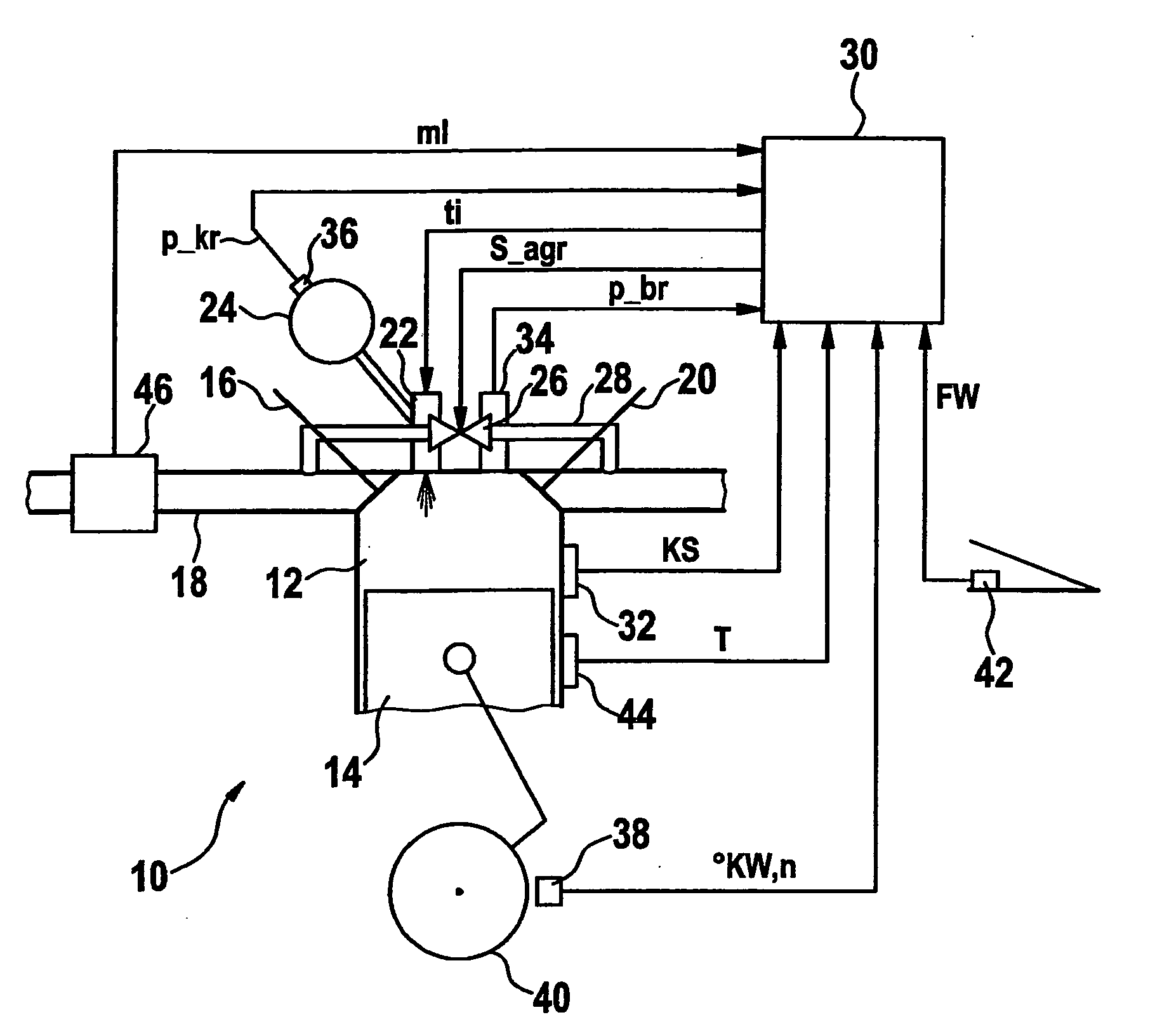
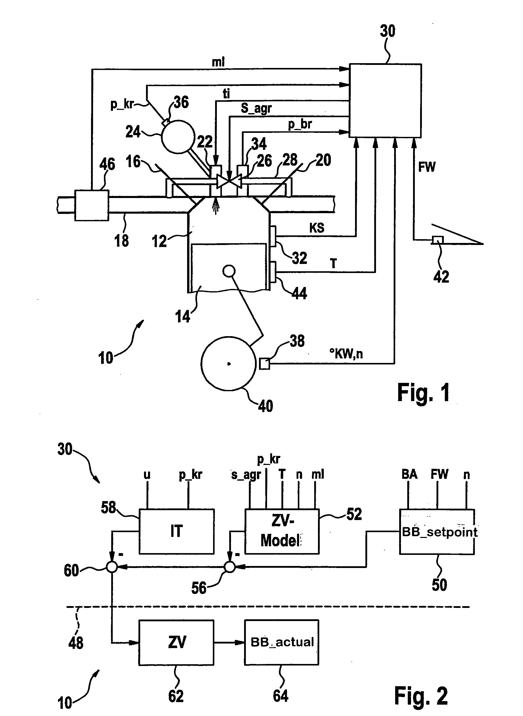
[0017]In particular, FIG. 1 shows a diesel engine 10 having at least one combustion chamber 12, which is movably sealed by a piston 14. Combustion chamber 12 is filled with air from an intake manifold 18 via an intake valve 16. Combusted gases are expelled via a discharge valve 20. Fuel from pressurized fuel reservoir 24 is injected via an injector 22 to the combustion chamber charge compressed in the compression cycle. Furthermore, exhaust gas is supplied to combustion chamber 12 via an exhaust gas recirculation valve 26 in exhaust gas recirculation 28. Injector 22 and exhaust gas recirculation valve 26 are controlled by a control unit 30, which processes signals of different sensors for this purpose. In FIG. 1, these are combustion feature sensors 32 and / or 34, a fuel pressure sensor 36, an angle sensor system 38 on a component 40 which rotates synchronously with the cycles of diesel engine 10, a driver's intent transducer 42, a temperature sensor 44, and an air mass flow meter 46...


PUM


Abstract

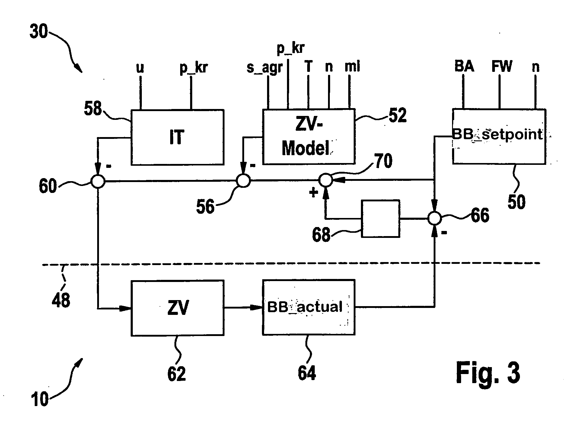
A method for controlling a fuel injector of a diesel engine having a predefined control time from a control start, in which a setpoint value of a combustion start of a combustion chamber charge of the diesel engine is ascertained. The method is characterized in that an ignition delay between the control start and the combustion start is estimated from performance parameters of the diesel engine using a computing model, and the control start is formed on the basis of the setpoint value of the combustion start and the estimated ignition delay. A control unit controls the sequence of the method.

Description

FIELD OF THE INVENTION[0001]The present invention relates to a method for controlling a fuel injector of a diesel engine having a predefined control time from a control start, a setpoint value for a combustion start of a combustion chamber charge of the diesel engine being ascertained. The present invention also relates to a control unit which controls the sequence of such a method.BACKGROUND INFORMATION[0002]Such a method and such a control unit are discussed in German patent document DE 195 36 110 A1. In this method, the setpoint value is determined from measured performance parameters of the diesel engine, an actual value is determined from signals of different sensors, and the actual value is regulated to the setpoint value in a closed loop. The manipulated variable for the regulation is activated at the beginning of a signal which triggers the injector for an injection. The beginning of this signal is referred to in the following as control start.[0003]Basic values for the cont...

Claims


Application Information

Patent Timeline
Patent Type & Authority Applications(United States)
IPC IPC(8): F02D41/30F02M25/07
CPCF02B3/06F02D35/025F02D35/028F02D41/0072Y02T10/44F02D41/401F02D2041/141F02D2041/1433F02D41/3035Y02T10/40
Inventor POLACH, STEFANTORKZADEH, DARA
Owner ROBERT BOSCH GMBH
Learn More