Anchoring in a construction model

a construction model and anchoring technology, applied in the construction field, can solve the problem of not being able to excite a known connecting element with sufficient vibratory energy to ensure a reliable anchoring by the known methods, and achieve the effect of increasing the pressure in the lateral direction, increasing the friction force, and solid anchoring

Active Publication Date: 2010-02-25
WOODWELDING
View PDF7 Cites 5 Cited by
  • Summary
  • Abstract
  • Description
  • Claims
  • Application Information

AI Technical Summary

Benefits of technology

[0021]The invention according to the first aspect treads a new path compared with the state-of-the-art technology. The state-of-the-art technology is familiar with methods of providing an opening in the object and subsequently anchoring the—e.g. roughly pin shaped—anchoring element in the opening by positioning it in the opening and applying ultrasonic vibration to it. During this process, the thermoplastic material of the anchoring element may be liquefied on the circumferential surfaces of the anchoring element and, if applicable, penetrate pores along the bore walls. However, it is found that the anchoring effect of this “non-pressurized” penetration into pores is often rather moderate. According to the state-of-the-art technology it is possible to achieve a lateral pressure by shaping the bore conically, which is elaborate. In contrast, according to the invention, pressure in a lateral direction is increased by the compression and accompanying enlargement of the distance between compression axis and a peripheral surface of the anchoring element. This, on the one hand, increases the friction forces generated on the circumferential anchoring element surface and causes the energy coupled into the anchoring element via the mechanical vibrations to induce a liquefaction of the thermoplastic material precisely in that region, i.e. laterally, along the circumferential surface. On the other hand the lateral pressure also drives the liquefied material into laterally existing pores or other structures (surface structures, cavities etc.) of the bore and thus results in a particularly solid anchoring.
[0022]Hence the anchoring element according to the invention makes it possible to exert pressure upon the lateral surfaces of the bore. This enables an anchoring of the anchoring element even in situations where no pressure can be applied to the bottom of the bore—e.g. because the object is very brittle and / or very thin—or where the bore has no bottom because it is through-going. In such a case, additional means for absorbing the compressing force must be provided. Such means are discussed in detail below.

Problems solved by technology

There are situations however, in which anchoring of connecting elements by mechanical vibrations according to the state-of-the-art technology does not suffice or in which, e.g. due to limited accessibility of the opening, it is not possible to excite a known connecting element with sufficient vibratory energy to ensure a reliable anchoring by the known methods.

Method used


Image

  • Anchoring in a construction model
  • Anchoring in a construction model
  • Anchoring in a construction model

Examples


Embodiment Construction

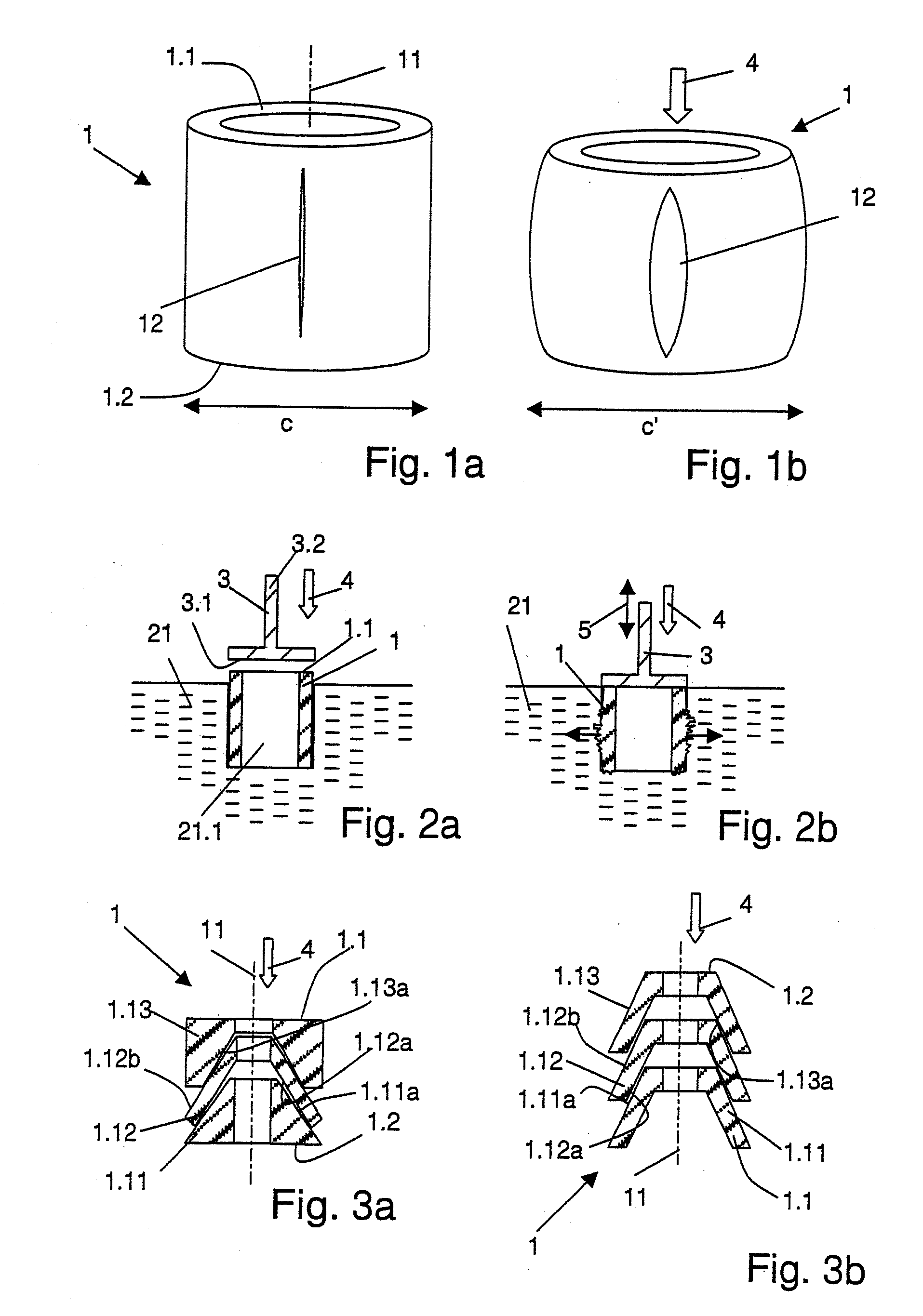
[0098]The anchoring element 1 according to FIG. 1a is a first example of an anchoring element according to the first aspect of the invention which is suitable as a coupling sleeve for attaching a fitting on the object. The anchoring element is essentially tubular, consists of a thermoplastic material, and comprises a proximal end face 1.1 and a distal end face 1.2. The anchoring element further comprises at least one slot 12 extending approximately parallel to the axis 11 of the anchoring element; advantageously there are two, three or more than three slots arranged approximately equidistantly. Due to the slot or slots 12 the anchoring element is compressible by a compressing force 4 acting parallel to its axis (according to FIG. 1a, the axis 11 of the tubular anchoring element is also its compression axis). The anchoring element is depicted in a compressed state in FIG. 1b.

[0099]It is obvious that for achieving the desired compression a force must act upon the anchoring element fr...


PUM

PropertyMeasurementUnit
mechanical frequencyaaaaaaaaaa
viscosityaaaaaaaaaa

Abstract

A method suitable for anchoring an anchoring element in an object, which anchoring element is compressible in the direction of a compression axis under local enlargement of a distance between a peripheral anchoring element surface and the compression axis. The anchoring element has a coupling-in face which serves for coupling the mechanical vibrations into the anchoring element, which coupling-in face is not parallel to the compression axis. The anchoring element further includes a thermoplastic material which in areas of the peripheral surface enlargement forms at least a part of the surface of the anchoring element, the method includes the steps of: providing a bore in the object; positioning the anchoring element in the bore; and coupling the compressing force and the mechanical vibrations through the coupling-in face into the positioned anchoring element.

Description

BACKGROUND OF THE INVENTION[0001]1. Field of the Invention[0002]The invention is in the field of construction, especially building industry, timber construction, furniture industry and mechanical construction and concerns a method of anchoring an anchoring element in an object of construction material, which object has a porous or structured surface, the object surface, into which the anchoring element is anchored, being of wood, a wood composite (such as chipboard, particle board, oriented strand board etc), cardboard, concrete, brick, plaster, stone (such as sandstone) or industrial hard foam, into which a liquefied material can penetrate under pressure. The invention also concerns a corresponding anchoring element to be anchored in an object, and a corresponding device.[0003]2. Description of Related Art[0004]Methods of anchoring connecting elements in an opening in a fibrous or porous building material with the aid of mechanical vibrations are known from publications such as WO ...

Claims


Application Information

Patent Timeline
Patent Type & Authority Applications(United States)
IPC IPC(8): E04B1/48F16B37/06F16B13/06
CPCB29C65/645B29C66/30326B29C66/47B29K2711/14F16B13/061Y10T29/49945Y10T24/45927F16B13/0841B29C66/474B29C65/7844Y10T403/16B29C65/00B29C66/8322B29C2793/0045B29C66/82261B29C66/7487B29C66/7463B29C65/08F16B13/06E04C5/12E04B1/388
Inventor AESCHLIMANN, MARCELTORRIANI, LAURENTLEHMANN, MARIOMAYER, JORG
Owner WOODWELDING
Why Eureka
Try Eureka