
Exhaust diffuser for a truck

a technology for exhaust diffusers and trucks, applied in the direction of pipes, mechanical equipment, machines/engines, etc., can solve the problems of difficulty in exhausting the higher temperature stream to the atmospher

Active Publication Date: 2010-02-25
VOLVO LASTVAGNAR AB
View PDF13 Cites 28 Cited by
  • Summary
  • Abstract
  • Description
  • Claims
  • Application Information

AI Technical Summary

Benefits of technology

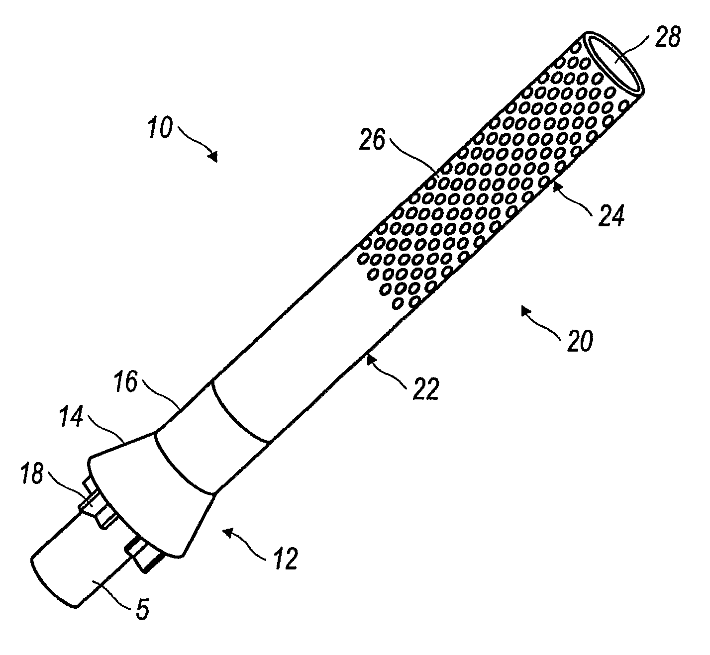
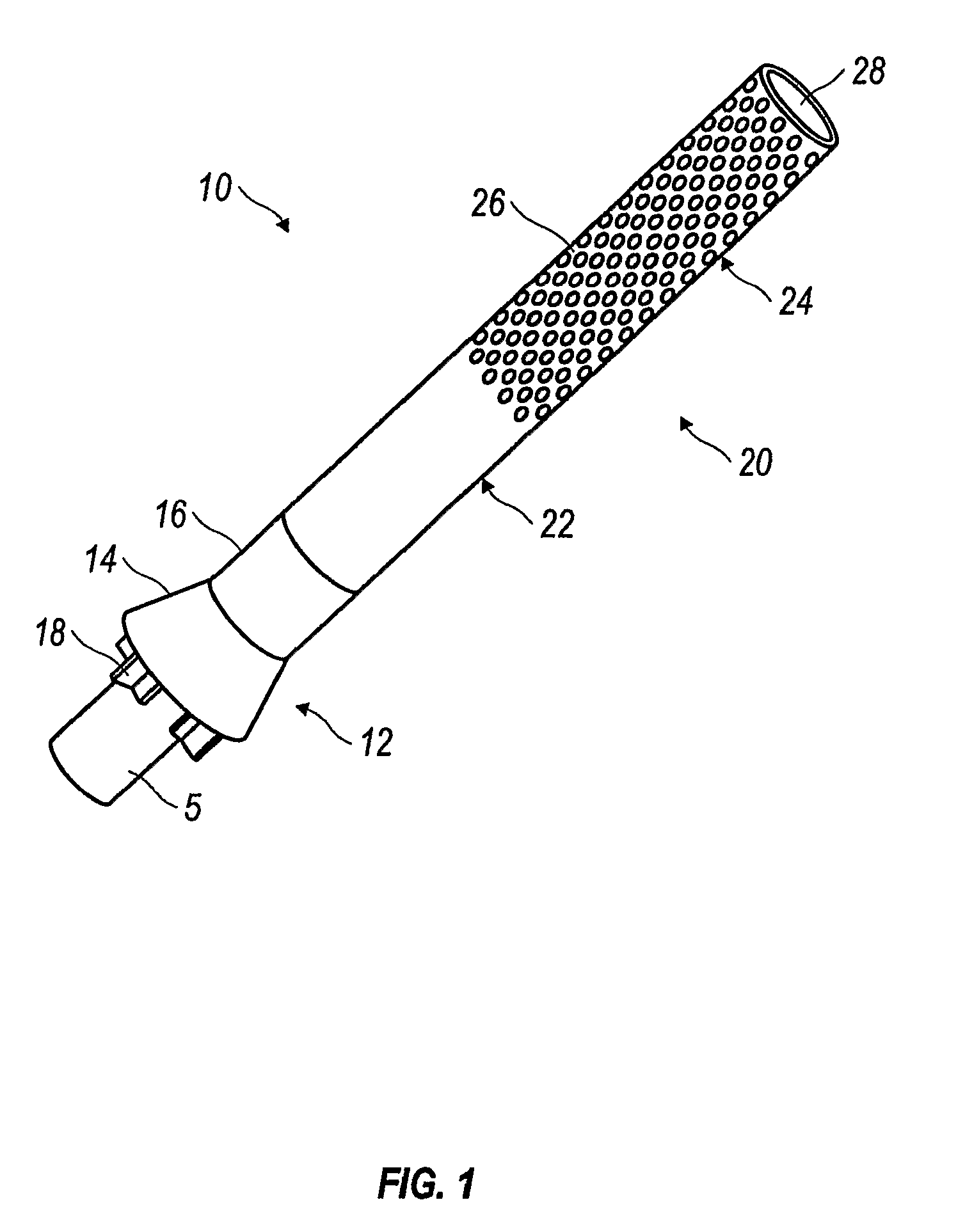
[0007]The diffuser device is mounted on the stack pipe and includes a diluter body that flares outward and extends over the DPF exhaust conduit or stack pipe. The flared body defines an annular cone space for an inlet to the device, which draws in ambient air to mix with the exhaust gases in a mixing section. Downstream of the mixing section is a diffuser section, which is preferably a section of perforated pipe. The exhaust gases are dissipated to the atmosphere through the perforated outlet pipe. The axial end of the outlet pipe is closed, which forces all exhaust gas to exit through the perforations. The total open area of the perforations is greater than the open area at the axial end of a standard five inch exhaust pipe, which also helps eliminate added back pressure. Preferably, the perforations in the pipe provide an exhaust area approximately 2.5 times the cross sectional area of a five inch exhaust pipe, which helps dissipate and diffuse the exhaust gases to atmosphere.
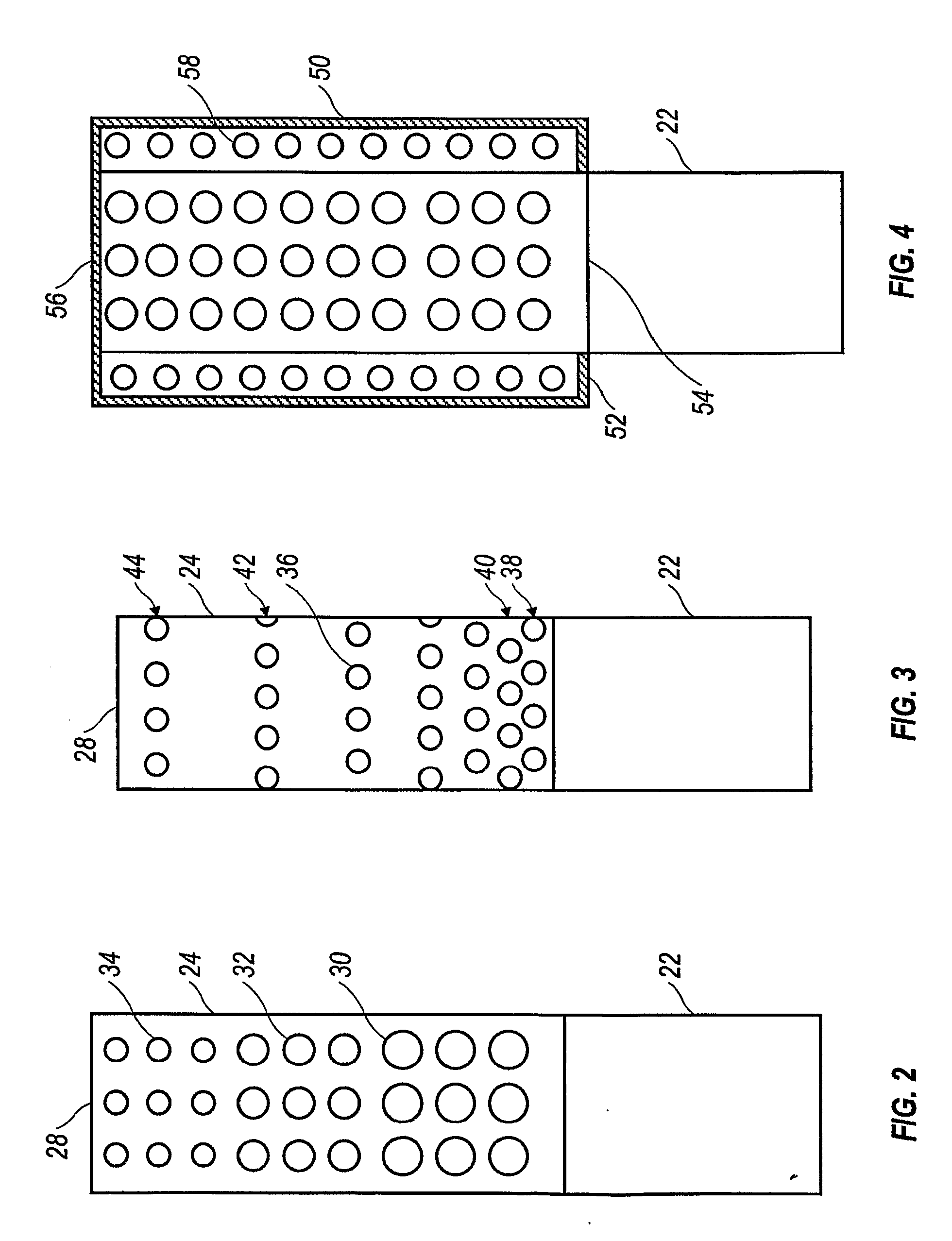
[0011]Alternatively, the hole pattern can be non-uniformly formed, with a greater density of open area at the upstream end of the diffuser and a lesser density of open area at the downstream end. Such an arrangement helps generate a uniform flow exiting the diffuser along the length of the diffuser. According to one embodiment, holes of larger diameter are positioned at the upstream end and holes of smaller diameter positioned at the downstream end. The holes may be sized to decrease by a factor, according to one embodiment, ½ the open area, for each step change. Conveniently, several rows of holes of each size may be provided.
[0013]To protect the cab from hot exhaust gas, the hole pattern of the diffuser may be positioned on a radially outwardly facing surface of the diffuser pipe section less than the full 360 degree surface. The hole pattern may be on a 180 degree radially outward portion or a 90 degree portion as advantageous to protecting the cab while providing sufficient open area for exhaust.
[0014]Another embodiment of the invention includes a perforated diffuser section having a perforated heat shield disposed about the diffuser section. The heat shield or secondary diffuser may be in the form of a cylindrical body being open at the bottom, upstream end, and having a cap at the downstream end. The cylindrical body is disposed over the diffuser section so that ends of the cylindrical body are closed or sealed, forcing exhaust to exit through the perforations. Hole patterns for the heat shield may be uniform or non-uniform. The heat shield is spaced from the diffuser a sufficient distance so that the temperature at the heat shield is not likely to ignite substances that may contact the shield.

Problems solved by technology

Exhausting the higher temperature stream to atmosphere poses difficulties.

Method used


Image

  • Exhaust diffuser for a truck
  • Exhaust diffuser for a truck
  • Exhaust diffuser for a truck

Examples


Embodiment Construction

[0024]The invention relates to devices that are mounted on the end of a truck exhaust system at the point where exhaust gas is released to the surrounding air. In particular, the invention is an apparatus mounted on an exhaust downstream of a diesel particulate filter to diffuse the hot gases over a wide area. According to another aspect of the invention, structure is provided to dilute exhaust gases with ambient air and diffuse the diluted exhaust gas over a wider area than a typical exhaust stack pipe to prevent hot spots and dissipate heat more quickly.

[0025]FIG. 1 shows an embodiment of a combined dilution and diffusing device. The diffuser / diluter 10 of FIG. 1 is mountable on a standard 5 inch exhaust stack pipe 5. The apparatus includes a diluter section, here formed as a venturi element 12 having flared skirt 14 leading to a straight tube 16. Standoffs 18 mount the venturi element 12 to the stack pipe 5 in a co-axial disposition. The tube 16 is wider than the stack pipe 5, wh...


PUM


Abstract

An exhaust diluting and diffusing apparatus includes a pipe mountable on a exhaust stack pipe, and having a flared skirt inlet to define an annular inlet, a mixing section adjacent the inlet, and an exhaust section formed as a pipe section with a multiplicity of holes. The apparatus pipe has a diameter greater than the diameter of the exhaust stack on which it is mounted.

Description

[0001]This application claims the benefit of U.S. Provisional Patent Application No. 60 / 842,842, filed Sep. 7, 2006.[0002]The invention relates to devices mounted on truck exhaust systems to dilute and diffuse the exhaust gas as it is released from the truckBACKGROUND[0003]Exhaust treatment devices in trucks require maintenance procedures that can create situations where exhaust temperatures are much higher than during normal use of the vehicle. For example, diesel particulate filters, which trap soot and other particulate matter in the exhaust stream, require a regeneration process to burn off the collected matter. The process requires that the temperature of the exhaust entering the diesel particulate filter be in excess of 600° C. Normal operating exhaust temperature is about 425° C. for a diesel engine in a truck.[0004]Exhausting the higher temperature stream to atmosphere poses difficulties. A truck typically has an exhaust stack pipe rising from the chassis adjacent to the tru...

Claims


Application Information

Patent Timeline
Patent Type & Authority Applications(United States)
IPC IPC(8): F01N3/02F16L9/18F16L9/14
CPCF01N13/082F01N2240/20F01N2590/08F01N2470/02F01N2470/04F01N2270/02
Inventor DICKINSON, HUGH THOMASLAFFERTY, CLINTON LANECORE, RAYVONN DONNELLMILLER, WILLIAM ROBERT
Owner VOLVO LASTVAGNAR AB
Learn More