Controller for internal combustion engine

a technology of controller and internal combustion engine, which is applied in the direction of electrical control, process and machine control, instruments, etc., can solve the problems of restricted increase in power consumption, improve controllability of high-pressure pumps around the maximum discharge amount, and reduce the effect of power consumption

Inactive Publication Date: 2010-02-25
DENSO CORP
View PDF13 Cites 3 Cited by
  • Summary
  • Abstract
  • Description
  • Claims
  • Application Information

AI Technical Summary

Benefits of technology

[0012]Since the energization period of the fuel pressure control valve is prolonged during a period in which the demand fuel discharge amount is greater than a specified amount, the energization period of the fuel pressure control valve is prolonged by a specified period when the demand fuel discharge amount is around the maximum discharge amount. Even if the energization of the fuel pressure control valve is expedited due to a tolerance variation of the crank angle sensor and a can angle sensor, when the demand fuel discharge amount is around the maximum discharge amount, the energization period of the fuel pressure control valve is prolonged in an advance direction until the fuel pressure in the pump chamber is increased to hold the closing position of the fuel pressure control valve. The controllability of the high-pressure pump around the maximum discharge amount is improved.
[0013]Alternatively, even if the energization period of the fuel pressure control valve is delayed due to a tolerance dispersion of sensors, when the demand fuel discharge amount is around the maximum discharge amount, the energization period of the fuel pressure control valve is prolonged in a retard direction in such a manner that a closing start timing of the fuel pressure control valve is brought closer to a bottom dead center of the plunger of the high-pressure pump. According to the present invention, since the conventional problems can be solved by prolonging the energization period of the fuel pressure control valve, a system configuration is not changed and a part of a soft ware is changed to employ the present invention, so that a demand of low cost is satisfied. Furthermore, when the demand fuel discharge amount is less than a specified amount, the energization period of the fuel pressure control valve is not prolonged. An increase in a power consumption is restricted.

Problems solved by technology

An increase in a power consumption is restricted.

Method used


Image

  • Controller for internal combustion engine
  • Controller for internal combustion engine
  • Controller for internal combustion engine

Examples


Embodiment Construction

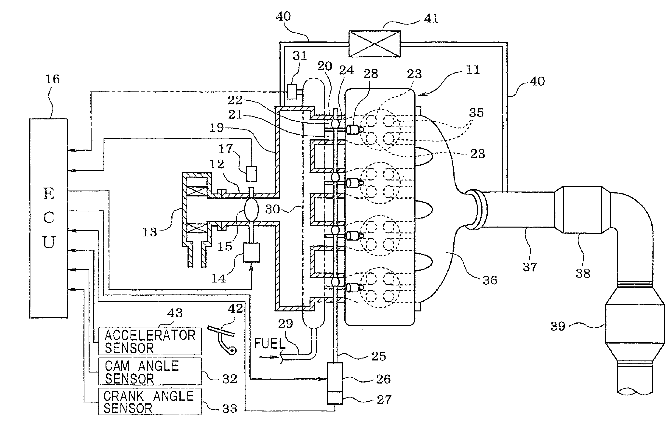
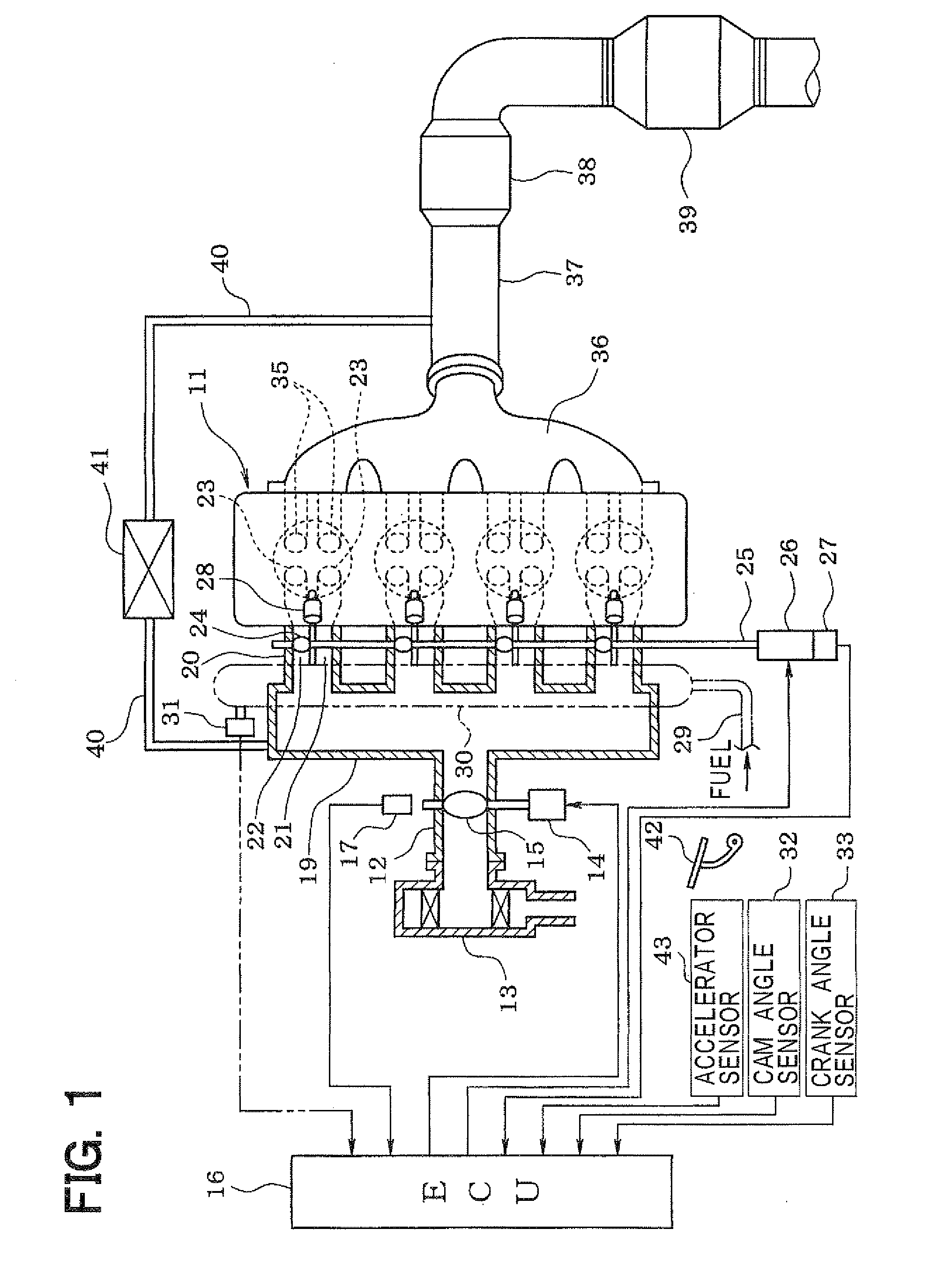
[0023]Hereafter, an embodiment of the present invention is described. Referring to FIG. 1, an engine control system is explained. An air cleaner 13 is arranged upstream of an intake pipe 12 of a direct injection engine 11. A throttle valve 15 is arranged downstream of the air cleaner 13. A motor 14 adjusts an opening degree of the throttle valve 15. An opening degree of the throttle valve 15 (throttle opening) is detected by a throttle opening sensor 17.

[0024]A surge tank 19 is provided downstream of the throttle valve 15. An intake air manifold 20 is connected to the surge tank 19 to introduce air into the engine 11. Each intake manifold 20 is divided into a first intake passage 21 and a second intake passage 22. The first intake passage 21 and the second intake passage 22 respectively connected to each of two intake ports 23.

[0025]An air flow control valve 24 is provided in the second intake passage 22 to control intensities of swirl flow and tumble flow. Each of the air flow cont...


PUM


Abstract

In a direct fuel injection, a fuel is pressurized by a high-pressure pump and is supplied to a fuel injector. The pressurized fuel is directly injected into a cylinder through a fuel injector. When it is determined that demand fuel discharge amount of the high-pressure pump is greater than a specified value, an energization period of a fuel pressure control valve is prolonged by a specified time period.

Description

CROSS-REFERENCE TO RELATED APPLICATION[0001]This application is based on Japanese Patent Application No. 2008-213126 filed on Aug. 21, 2008, the disclosure of which is incorporated herein by reference.FIELD OF THE INVENTION[0002]The present invention relates to a controller for a direct injection engine in which fuel is pressurized and is injected into the cylinder directly.BACKGROUND OF THE INVENTION[0003]Recently, various direct injection engines have been developed. In the direct injection engine, in order to expedite an atomization of the fuel, the fuel is highly pressurized. JP-8-303325A shows a direct injection engine in which the fuel pumped by a low-pressure pump from a fuel tank is pressurized by a high-pressure pump, which is driven by a camshaft of the engine. The pressurized fuel is supplied to a fuel injector.[0004]In such a direct injection engine with the high-pressure pump, by controlling a closing time of a fuel pressure control valve provided in the high-pressure p...

Claims


Application Information

Patent Timeline
Patent Type & Authority Applications(United States)
IPC IPC(8): F02M59/36F02D41/00
CPCF02D41/20F02M59/366F02D2041/2031F02D41/3845
Inventor HIRATA, YASUO
Owner DENSO CORP
Why Eureka
Try Eureka