
Photoinitiated optical adhesive and method for using same

Active Publication Date: 2010-02-25
MFG RESOURCES INT INC
View PDF14 Cites 6 Cited by
  • Summary
  • Abstract
  • Description
  • Claims
  • Application Information

AI Technical Summary

Benefits of technology

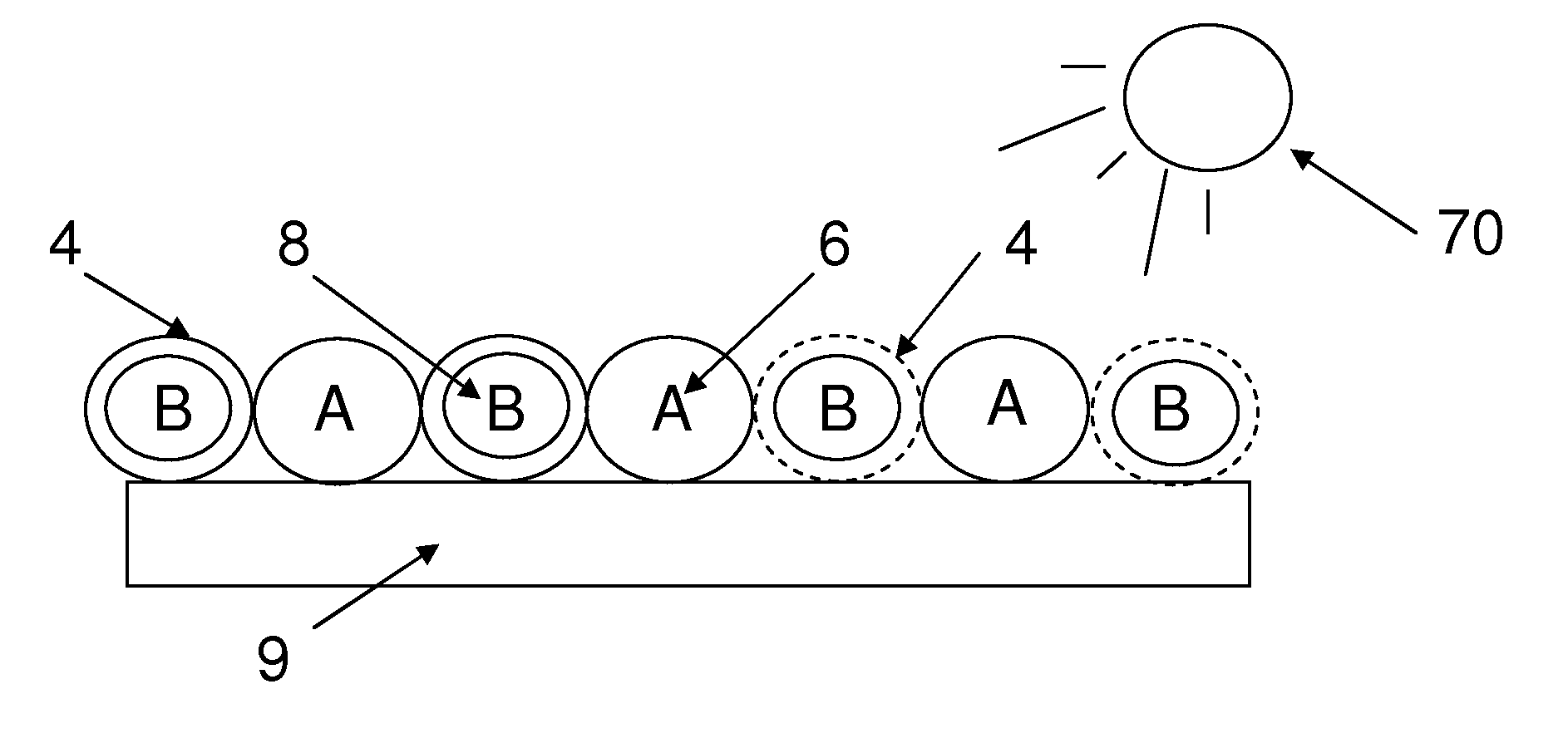
[0008]These and other problems related to traditional optical display adhesives may be eliminated through the use of the exemplary embodiments described herein. In one exemplary embodiment an encapsulated two part photo-initiated adhesive may be used to bond glass components of a display. The adhesive may comprise a first part being a resin (hereinafter “part A”, “resin portions”, or “resin”) and a second part being a catalyst (hereinafter “part B”, “catalyst portions”, or “catalyst”) (collectively “components”). As the adhesive resulting from the combination of resin and catalyst may be used to optically bond glass components of a display, the adhesive would preferably be substantially transparent and provide minimal image distortion. Platinum catalysts have been found to provide a suitable optical adhesive. The curing process of platinum group catalysts may be found in U.S. Pat. Nos. 5,548,038 filed on Mar. 14, 1995; and 5,661,210 filed on Sep. 25, 1996, incorporated herein by reference in their entirety.
[0009]To prevent prema

Problems solved by technology

Traditional adhesives and bonding processes are time consuming and are subject to problems / defects resulting in a display unfit for consumer use.
This immediate curing significantly reduces the workable time of the mixture.
The short workable time of the material may lead to various defects in the display.
One such problem with traditional methods is the formation of air bubbles in the adhesive.
As the optical adhesive is interposed between two glass components, the display would be ruined if bubbles were present.
Another problem that may occur during the bonding process is known as the halo effect or window framing.
The halo effect may be caused by using an insufficient amount of adhesive to maintain glass component coverage during the curing phase.
As the optical adhesive cures and experiences shrinking, the adhesive may pull away from the edges of the bonded glass components, resulting in both mechanical and optical failures.
Insufficient amounts of adhesive could also lead to mechanical separation of the glass components.
In addition, the immediate curing may not allow for the glass components to be readjusted after coming into contact with the adhesive.
When defects in the finally assembled glass are present, the only options left to manufacturers are to either dispose of the rejected components or spend large amounts of time manually removing the adhesive from the glass components.
These problems are now magnified as the size of LCD displays are becoming larger and larger which necessitate the need for larger, more expensive glass components.
Although these adhesives may provide benefits over traditional mix cured adhesives, some problems still exist.
One such problem is the increased cost of production due to the need to maintain the UV light during the curing phase.
Another problem is that display features such as grid heaters, anti-reflective layers, or other devices may prevent the UV light from reaching the entire adhesive.
The result may be that portions of the adhesive are not cured properly and thus weaken the bond.
This weakness may result in increased mechanical separation and image distortion as a result of the uncured adhesive.

Method used


Image

  • Photoinitiated optical adhesive and method for using same
  • Photoinitiated optical adhesive and method for using same
  • Photoinitiated optical adhesive and method for using same

Examples


Embodiment Construction

)

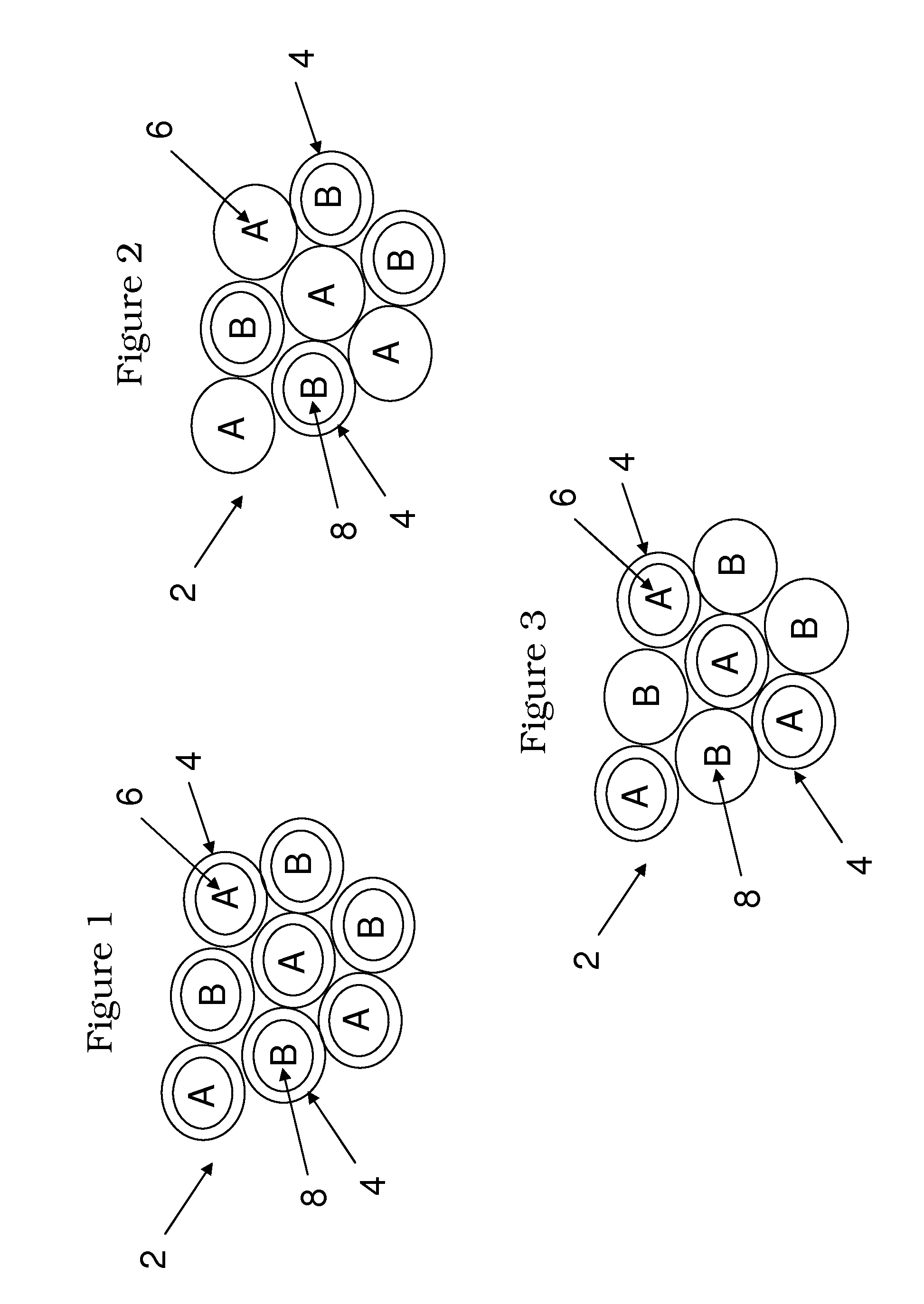
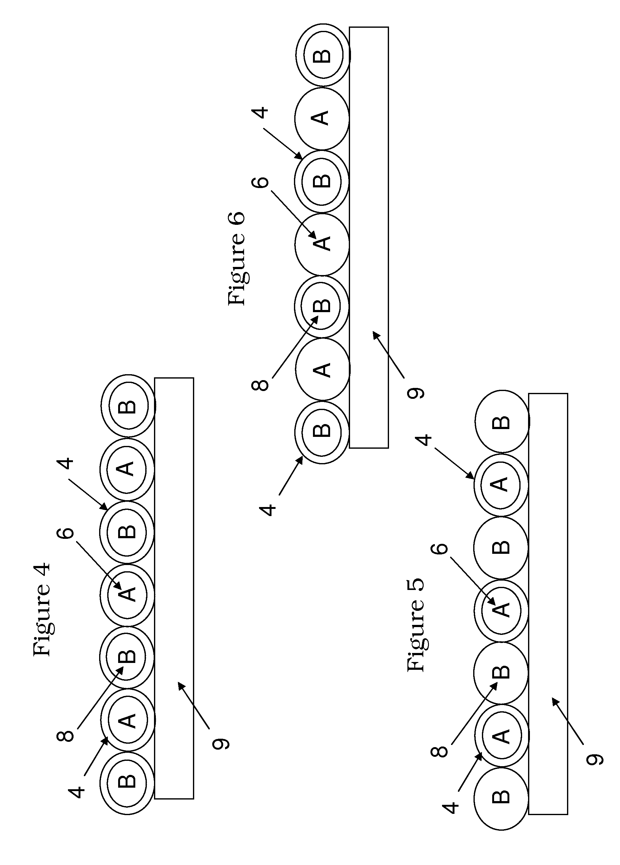
[0037]FIG. 1 illustrates an exemplary embodiment of a mixture 2 comprising capsules 4. The capsules 4 may contain either a resin portion 6 or a catalyst portion 8. The capsules 4 may also contain any other material or additive necessary to facilitate adhesive formation between the resin portions 6 and the catalyst portions 8. The capsules 4 prevent the resin portions 6 and the catalyst portions 8 from coming into direct contact with one another. The use of the capsules 4 allows the resins portions 6 and the catalyst portions 8 to be premixed eliminating the need to mix multi-part adhesives during the bonding process.

[0038]FIGS. 2 and 3 illustrate other exemplary embodiments of the mixture 2. FIG. 2 illustrates a mixture 2 wherein only part B 8 is encapsulated. FIG. 3 illustrates a mixture 2 wherein only part A 6 is encapsulated. By providing a capsule 4 (encapsulating element) around either part A 6 or part B 8, the components remain isolated from one another. An advantage of encap...


PUM

PropertyMeasurementUnit
Thicknessaaaaaaaaaa
Perimeteraaaaaaaaaa

Abstract

A method for bonding glass components using an encapsulated photo-initiated optical adhesive, and the resulting glass assemblies produced by the same. A mixture containing a catalyst and a resin is provided where at least one of either the catalyst or the resin is encapsulated. The mixture is applied to a glass component. The encapsulated catalyst may then be exposed to ultraviolet light causing the capsules to release the portions contained therein and combine to form an adhesive. A second glass component is then placed on the adhesive so that the adhesive is interposed between the glass components and the adhesive is permitted to cure. Alternatively, the mixture may be exposed to UV light after the second glass component is placed. An exemplary method uses a frame with the first glass component to create a uniform thickness of adhesive and provide a low level of optical defects. Barrier coats and skirting tape may also be used.

Description

CROSS-REFERENCE TO RELATED APPLICATIONS[0001]This application is a non-provisional and claims priority to provisional application No. 61 / 081,722 filed on Jul. 17, 2008. This application is also a CIP of non-provisional application Ser. No. 12 / 125,046, filed on May 21, 2008. These applications are herein incorporated by reference in their entirety.TECHNICAL FIELD[0002]Exemplary embodiments relate generally to optical bonding in the manufacturing of displays.BACKGROUND AND SUMMARY OF THE INVENTION[0003]In the manufacturing of LCD displays, it is necessary to bond glass components to one another. The bonded glass components may be used in the formation of LCD stacks, glass front plates, lamination of touch panels, and other glass features found in LCD displays. Generally, glass components are bonded using an optical adhesive interposed between the glass components. Traditional adhesives and bonding processes are time consuming and are subject to problems / defects resulting in a display ...

Claims


Application Information

Patent Timeline
IPC IPC(8): B32B37/26
CPCB32B17/10706C03C27/10B32B17/10899B32B7/12
Inventor DUNN, WILLIAMLECAVE, MICHAEL
Owner MFG RESOURCES INT INC
Learn More