Hydrogen gas-cooling device

Inactive Publication Date: 2010-02-25
TAIYO NIPPON SANSO CORP
View PDF13 Cites 9 Cited by
  • Summary
  • Abstract
  • Description
  • Claims
  • Application Information

AI Technical Summary

Benefits of technology

[0020]According to the present invention, with the cooling of a hydrogen gas within the heat exchanger, a part of the liquefied gas within the outer pipe is evaporated, and the overall apparent density decreases. Therefore, the evaporated liquefied gas is spontaneously moved upward, and the liquefied gas is spontaneously circulated between the heat exchanger and the head tank. In this way, the liquefied gas is always moved within the overall outer pipe, resulting in the increase in the film heat-transfer coefficient on the side of the liquefied gas and the decrease in the necessary heat-transfer area. Accordingly, the heat transfer can be downsized, and the power for the supply of the liquefied gas is unncessary. In addition, the heat loss in the steady state is small, and therefore, the consumption quantity of the liquefied gas can be reduced.
[0021]By using the heat exchanger with the double pipe structure, the spacing between the outer pipe and the inner pipe therein can be shortened to for example ab

Problems solved by technology

However, in the aforementioned hydrogen gas-cooling device, there are problems in that the overall facilities are enlarged, the con

Method used


Image

  • Hydrogen gas-cooling device
  • Hydrogen gas-cooling device

Examples


Embodiment Construction

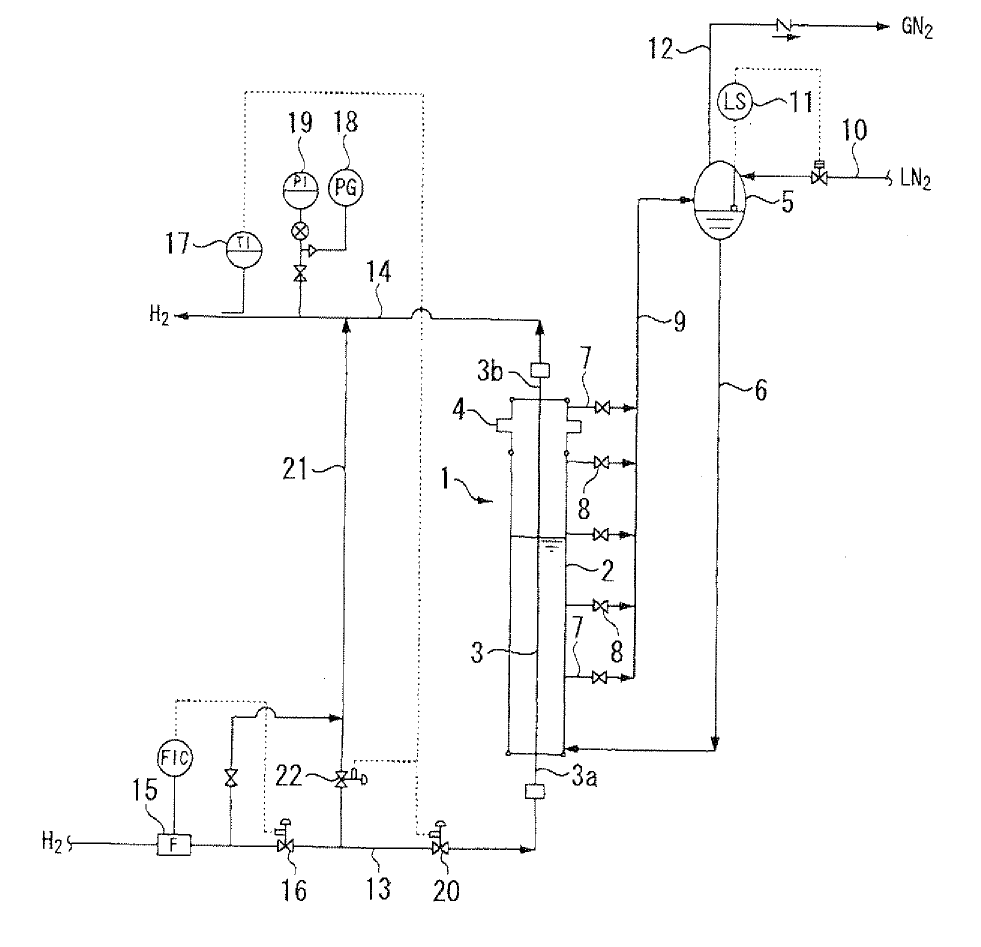
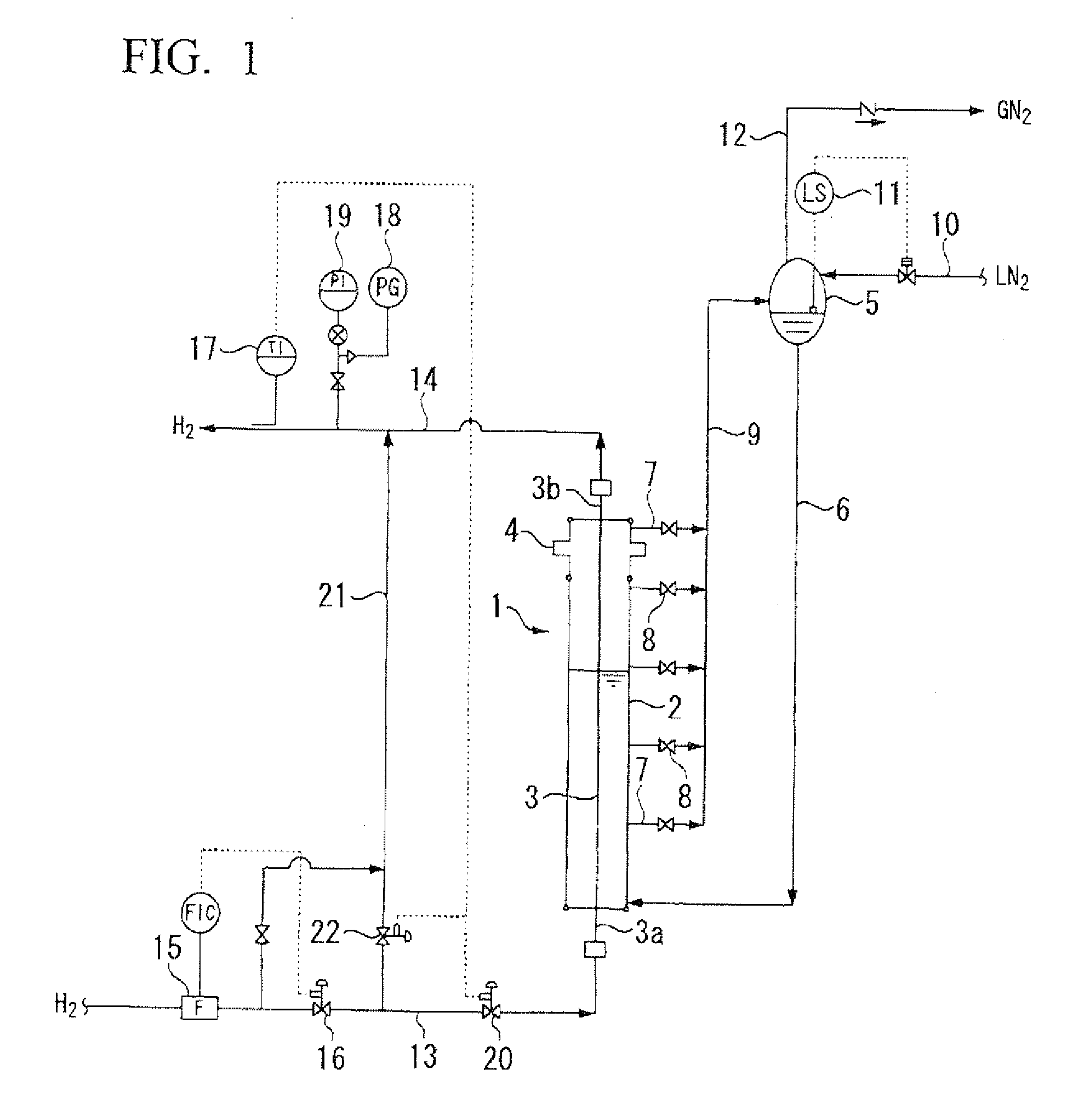
[0026]FIG. 1 represents an example of the hydrogen-cooling device of the present invention. In FIG. 1, the reference symbol 1 represents the heat exchanger. This heat exchanger 1 has the double pipe structure formed of the straight pipe-shaped outer pipe 2 and the straight pipe-shaped inner pipe 3 that is coaxially provided within the outer pipe 2.

[0027]This heat exchanger 1 is positioned in the sanding state in which the axes of the outer pipe 2 and the inner pipe 3 are arranged vertically or in the direction that is slightly tilted from the vertical direction.

[0028]The outer pipe 2 has the function of storing the liquefied gas therein which acts as a refrigerant such as liquid nitrogen, and is formed of a stainless steal with an inner diameter of 40-60 mm, an outer diameter of 45-80 mm, and a length of 500-2,000 mm The upper pact of his outer pipe 2 forms the bellows 4 that can elongate and contract in the longitudinal direction. Herein, the position of this bellows 4 is not limit...


PUM


Abstract

A hydrogen gas-cooling device of the present invention includes, a heat exchanger that perform beat exchange between a hydrogen gas and a liquefied gas to cool a hydrogen gas; and a head tank that stores the liquefied gas supplied to the heat exchanger, wherein the heat exchanger has double pipe structure in which the hydrogen gas flows in an inner pipe, an outer pipe is filled with the liquefied gas, the pipe axis of the double pipe structure is vertically or obliquely arranged, a liquefied gas supply pipe that supplies the liquefied gas from the head tank is connected to a bottom part of the outer tube, and a return pipe that returns the liquefied gas to the head tank is provided at a position upper than that of the bottom part of the outer pipe.

Description

TECHNICAL FIELD[0001]The present invention relates to a hydrogen gas-cooling device that is used to cool a hydrogen gas to be supplied to a hydrogen automobile, etc.[0002]Priority is claimed on Japanese Patent Application No. 2007-111562, filed Apr. 20, 2007, the content of which is incorporated herein by reference,BACKGROUND ART[0003]In a hydrogen automobile, it is required to fill a fuel tart with a hydrogen gas with a high pressure. When a fuel tank is filled with a hydrogen gas) the increase in the temperature occurs due to adiabatic compression. Moreover, a hydrogen gas is different from other conventional gases, and has the property that the adiabatic compression thereof causes the increase in the temperature due to Joule-Thomson effect.[0004]When the supply flow rate of a hydrogen gas is set high in order to improve the efficiency of filling operation, it is required to cool a hydrogen gas to a range from −30° C. to −40° C. before filling a fuel tank because the temperature o...

Claims


Application Information

Patent Timeline
IPC IPC(8): F28D7/10F17C5/06
CPCF25D3/10F28D7/0066Y02E60/321F28D2021/0047F28D7/106Y02E60/32F17C5/06F28D7/10F28F1/08
Inventor KOJIMA, NOBUYUKI
Owner TAIYO NIPPON SANSO CORP
Why Eureka
Try Eureka