Magnetic nanoparticle cellulose material

a technology of cellulose and nanoparticles, applied in the field of magnetic nanoparticle cellulose materials, can solve the problems of uneven distribution of nanoparticle systems, severe agglomeration and aggregates of nanoparticles, and poor representation of micron-sized filler materials in polymers, and achieve high mechanical performance nanoparticles, low apparent density, and reproducibility. high

Inactive Publication Date: 2010-08-12
CELLUTECH
View PDF6 Cites 14 Cited by
  • Summary
  • Abstract
  • Description
  • Claims
  • Application Information

AI Technical Summary

Benefits of technology

[0011]It is therefore an advantage of the invention to provide a new method and a magnetic nanoparticle cellulose material with ordered interconnected organic and inorganic phases on the nano-scale. Further, the new magnetic nanoparticle cellulose material with a network of cellulose nanofibres as scaffold can be used for the production of new functional nano-materials. Further, it can be used for in-situ precipitation of inorganic nanoparticles within the cellulose network, to produce evenly distributed nanoparticles inside an organic matrix and to prepare nano-functional lightweight “foam-like” materials with very low apparent density based on bacterial cellulose and provide possibilities to prepare magnetic hydrogels based on cellulose.
[0012]In one embodiment the new method provides possibilities to prepare high mechanical performance nanoparticle functional hybrid films. In another embodiment cast three-dimensional magnetic polymer composites are provided. Such composites are obtained by impregnation of the scaffold by a polymer, prepolymer or monomer liquid, followed by solidification
[0013]The magnetic nanoparticle cellulose material can be used within a broad range of applications. To illustrate the broad application area a number of different applications are suggested below without being limited in any way. The magnetic nanoparticle cellulose material can be used within the acoustical industry (loud-speaker membrane), magnetic filtration systems, chemical analysis methods, separation methods, etc.
[0014]Other advantages of the invention is to provide products such as; superfine magnetic filters / sieves, magnetic filtration set-ups activated by external field, catalytic support structures high-sensitivity magnetic membranes, magnetic films with uniformly / evenly distributed nanoparticles, microwave absorbers, magnetic foams based on nanoparticles, support structure for ferro-fluid based dampeners and template structures for fabrication of nanocomposites characterized by evenly distributed nanoparticles, i.e. sensitive electromagnetic switches, generators, magnetic actuators, magnetic storage media, etc.
[0015]The method makes it possible to produce highly reproducible magnetic nanoparticle cellulose material.
[0016]In a yet another embodiment the use of the polymer magnetic nanoparticle cellulose material provides a new type of “nanocomposite” where all constituents are dimensioned in the nano-scale range and the inorganic nanoparticle phase is distributed inside the material (cellulose nanofibre network). Since the bacterial cellulose hydrogel is a readily available material with high mechanical integrity due to the nanometrically scaled fibrils, the invented material with its possibilities to be modified for specific applications becomes particularly interesting. Additional modifications on top of what has been described above can also be made due to the facile direct impregnation of the freeze-dried bacterial cellulose. Various monomers can be used for in-situ polymerization / cross-linking after impregnation of the freeze-dried aerogel. Reactive monomers can effectively be soaked in to the material and crosslinked inside the material in order to create a rigid matrix material. Such modifications can potentially improve the functionalized material.

Problems solved by technology

Considering the potentially large area of application of magnetic nanoparticles, as filler materials of various polymer materials, it can easily be understood that their relatively poor representation in comparison to micron-sized filler materials in polymers is an effect of the difficulties related to the processing of high-surface area nanoparticles.
The explanation mainly lies in the fact that large surface areas also brings problems in achieving evenly distributed nanoparticle systems due to the favoured particle-particle interaction in comparison to particle-polymer / liquid interactions.
The result is often severe agglomeration and aggregates of nanoparticles.
In order to exploit the effects of nano-sized magnetic nanoparticles employed as fillers in organic matrix materials, the control over dispersion is therefore an unavoidable prerequisite.
Agglomeration of magnetic nanoparticles can be explained as a result of short-range isotropic forces and long-range anisotropic forces as well as poor compatibility between the surface of the inorganic nanoparticles and the matrix material.
However, as the majority of liquids and polymer systems exhibit various degree of polarity, the dispersion of magnetic nanoparticles is not simply solved by surface modifying the nanoparticles with one coating due to the fact that the surface coating with optimal solubility for a specific liquid polymer system is not the same for different system with different chemical character.
In addition, the coating procedure of the magnetic nanoparticles can potentially make dispersion even more difficult due to the potential risk of obtaining coated agglomerates rather than single particles.
Considerably stronger agglomerates are formed when the particles are dried, i.e. it is extremely difficult to distribute these particles in polymers.
Agglomeration is a major problem since the magnetic properties of a hybrid material on a macroscopic scale depend on the degree of agglomeration and is related to the degree of exchange coupling and dipolar forces between particles in the hybrid material.
But there are several problems with this technique such as not only one coating works in all situations for different polymers and no solution has been suggested how to optimize the coating in respect of the polymer matrix to have an optimal solubility.
(Ferrite-loaded membranes of microfibrillar Bacterial Cellulose Prepared by in Situ Precipitation. Chem. Mater., Vol. 10, No. 7, 1998), relates to microfibrillar bacterial cellulose prepared in situ and discusses that the preparation of a uniform nanocomposite is extremely difficult.
However, the transmission electron micrograph illustrates that the agglomeration problem persists.

Method used


Image

  • Magnetic nanoparticle cellulose material
  • Magnetic nanoparticle cellulose material
  • Magnetic nanoparticle cellulose material

Examples


example 1

CoFe2O4

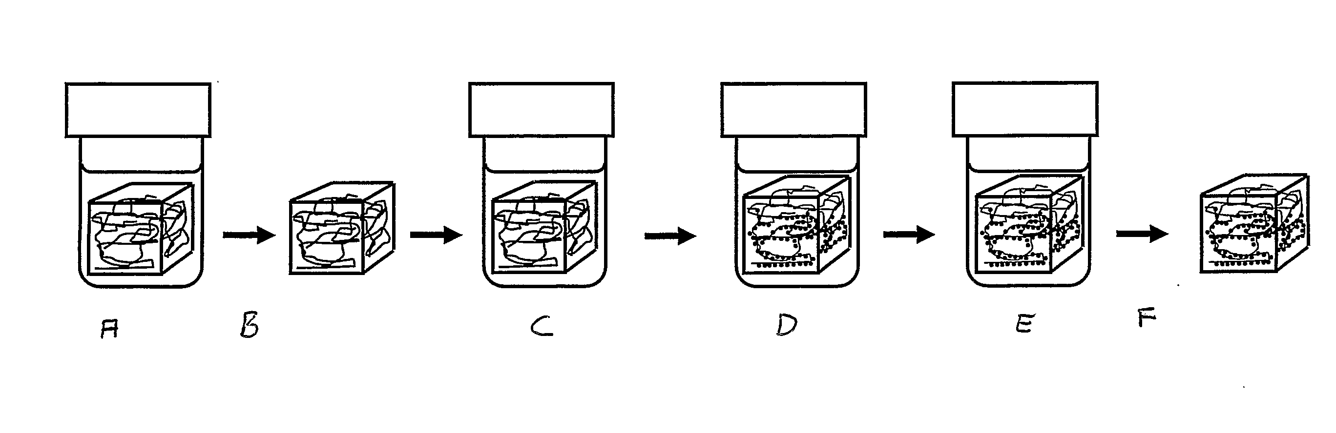
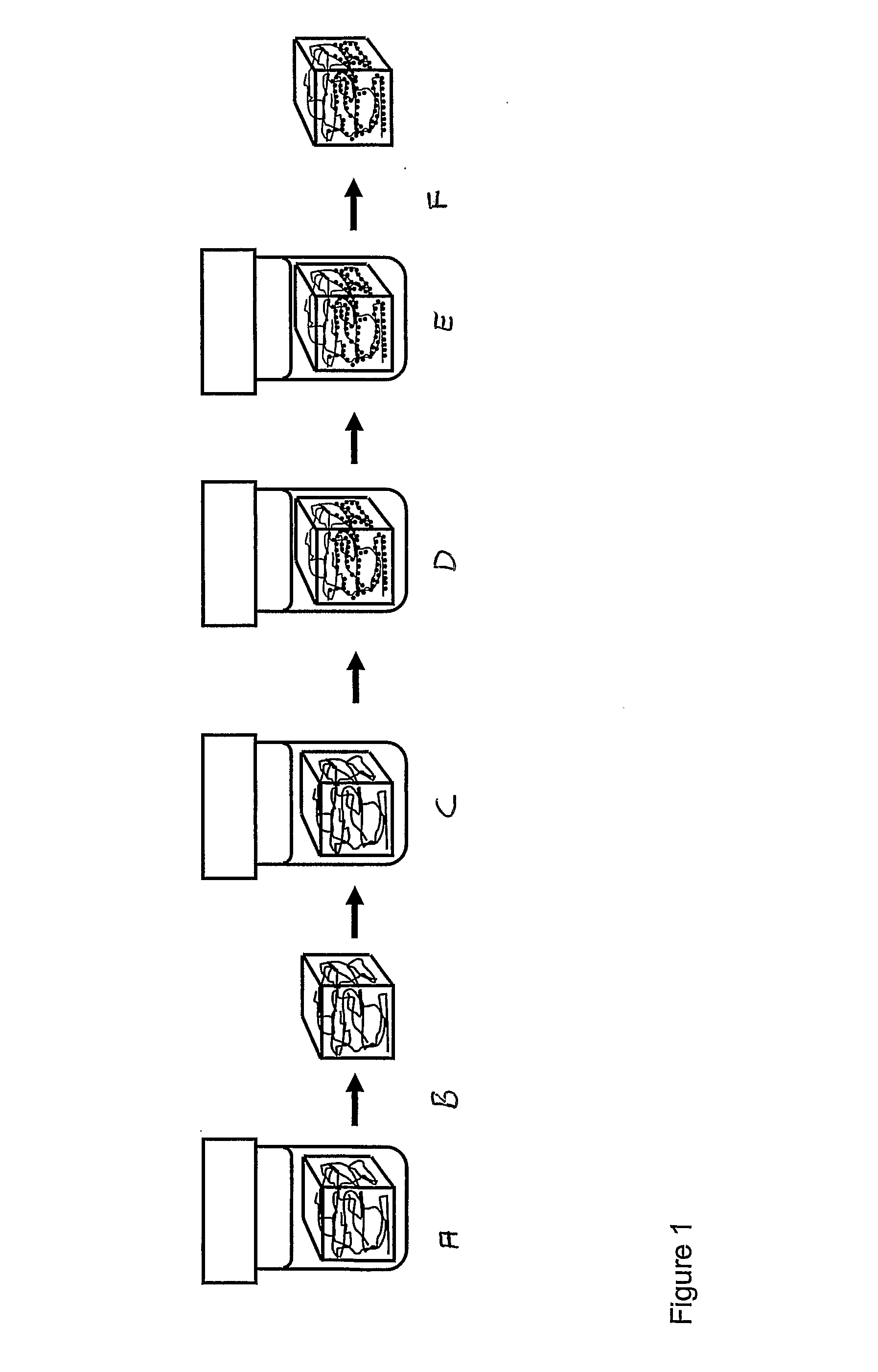
[0081]Precipitation of cobalt ferrite to form nanocrystals on the nanofibres of the bacterial cellulose.[0082]1. A piece of gel-like bacterial cellulose (0.5×0.5×1.5 cm) is boiled with 10 vol % NaOH solution (3 h) and sub sequentially washed with running distilled water (6 h) before immersion in liquid nitrogen followed by freeze-drying during a period of 12 hours.[0083]2. The dry cellulose piece is swollen in freshly prepared MilliQ-water solution of metal salt consisting of CoCl2×6H2O (0.033 M) and FeSO4×7H2O (0.66 M), i.e. stoichiometric proportions of Co:Fe (1:2).[0084]3. The solutions with the immersed pieces of cellulose is heated to 90° C. and kept at 90° C. for 3 h in order to thermally force the precipitation of the iron / cobalt salt solution to the related hydroxide / oxide structures of the cobalt / iron ions inside the matrix network of the bacterial cellulose.[0085]4. The piece is transferred into a 90° C. solution of NaOH (1.32 M) with KNO3 (0.15 M) ; ([Fe2+]* / [NO3−...

example 2

CoFe2O4

[0090]1. A piece of gel-like bacterial cellulose (0.5×0.5×1.5 cm) is boiled with 10 vol % NaOH solution (3 h) and sub sequentially washed with running distilled water (6 h) before immersion in liquid nitrogen followed by freeze-drying during a period of 12 hours.[0091]2. The dry cellulose piece is swollen in freshly prepared MilliQ-water solution of metal salt consisting of CoCl2×6H2O (0.055 M) and FeSO4×7H2O (0.11 M), i.e. stoichiometric proportions of Co:Fe (1:2).[0092]3. The solutions with the immersed pieces of cellulose is heated to 90° C. and kept at 90° C. for 3 h in order to thermally force the precipitation of the iron / cobalt salt solution to the related hydroxide / oxide structures of the cobalt / iron ions inside the matrix network of the bacterial cellulose.[0093]4. The piece is transferred into a 90° C. solution of NaOH (1.32 M) with KNO3 (0.25 M); ([Fe2+]* / [NO3−]=0.44). The piece is kept in this alkaline solution, which is maintained at 90° C. for 6 h.[0094]5. The...

example 3

CoFe2O4

[0098]1. A piece of gel-like bacterial cellulose (0.5×0.5×1.5 cm) is boiled with 10 vol % NaOH solution (3 h) and sub sequentially washed with running distilled water (6 h) before immersion in liquid nitrogen followed by freeze-drying during a period of 12 hours.[0099]2. The dry cellulose piece is swollen in freshly prepared MilliQ-water solution of metal salt (saturated) prepared by dissolving CoCl2×6H2O (0.33 M) and FeSO4×7H2O (0.66 M), i.e. stoichiometric proportions of Co:Fe (1:2).[0100]3. The solutions with the immersed pieces of cellulose is heated to 90° C. and kept at 90° C. for 3 h in order to thermally force the precipitation of the iron / cobalt salt solution to the related hydroxide / oxide structures of the cobalt / iron ions inside the matrix network of the bacterial cellulose.[0101]4. The piece is transferred into a 90° C. solution of NaOH (1.32 M) with KNO3 (1.5 M); ([Fe2+]* / [NO3−]=0.44). The piece is kept in the alkaline solution at 90° C. for 6 h.[0102]5. The pie...


PUM

PropertyMeasurementUnit
to particle inter-distanceaaaaaaaaaa
diameteraaaaaaaaaa
sizeaaaaaaaaaa

Abstract

The present invention relates to ferromagnetic materials based on nano-sized bacterial cellulose templates. More specifically, the present invention provides an agglomerate free magnetic nanoparticle cellulose material and a method of forming such magnetic nanoparticle cellulose material. Further, the magnetic nonoparticles are physically attached on the cellulose material and evenly distribute.

Description

BACKGROUND OF THE INVENTION[0001]Magnetic nanoparticles with large surface to bulk ratio is a growing area of interest. Considering the potentially large area of application of magnetic nanoparticles, as filler materials of various polymer materials, it can easily be understood that their relatively poor representation in comparison to micron-sized filler materials in polymers is an effect of the difficulties related to the processing of high-surface area nanoparticles. The explanation mainly lies in the fact that large surface areas also brings problems in achieving evenly distributed nanoparticle systems due to the favoured particle-particle interaction in comparison to particle-polymer / liquid interactions. The result is often severe agglomeration and aggregates of nanoparticles. The agglomerates in turn affect many macroscopic properties, such as mechanical, optical and magnetic etc. since these properties on a macroscopic scale are affected by the degree of close interaction at ...

Claims


Application Information

Patent Timeline
Patent Type & Authority Applications(United States)
IPC IPC(8): B32B5/02B05D5/12B32B5/16
CPCC08J5/005H01F1/0063C08J3/14B82Y25/00Y10T428/25Y10T428/298C08J2301/02B82Y30/00C08J3/215Y10T428/12028Y10T428/2982H01F1/375Y10T428/12035Y10T428/249921Y10T428/249965Y10T442/2762Y10T442/277Y10T442/2869
Inventor OLSSON, RICHARD T.AZIZI, MY AHMED SAID SAMIRBERGLUND, LARSGEDDE, ULF W.
Owner CELLUTECH
Why Eureka
Try Eureka