Multibeam Antenna System

a multi-beam antenna and antenna technology, applied in the field of beamforming antenna systems, can solve the problems of large antenna installation and installation costs, and large surface area increase, so as to maximise the antenna gain and directivity

Inactive Publication Date: 2010-02-25
APPLE INC
View PDF7 Cites 33 Cited by
  • Summary
  • Abstract
  • Description
  • Claims
  • Application Information

AI Technical Summary

Benefits of technology

[0029]Embodiments according to this further aspect of the invention offer a use of the transmitters/combiner/antennas/receiver configuration that is not limited to space division multiplexing, and one that involves selection of only one of the radio signals transmitted from t

Problems solved by technology

Modem wireless communications systems place great demands on the antennas used to transmit and receive signals, especially at cellular wireless base stations.
If a communication link is established to a user then other communication links established on other antenna beams represent interference to that user.
As a result, there is potentially a large increase in the total surface area of antennas deployed at a cell site in systems that employ space division multiplexing.
This

Method used


Image

  • Multibeam Antenna System
  • Multibeam Antenna System
  • Multibeam Antenna System

Examples


Embodiment Construction

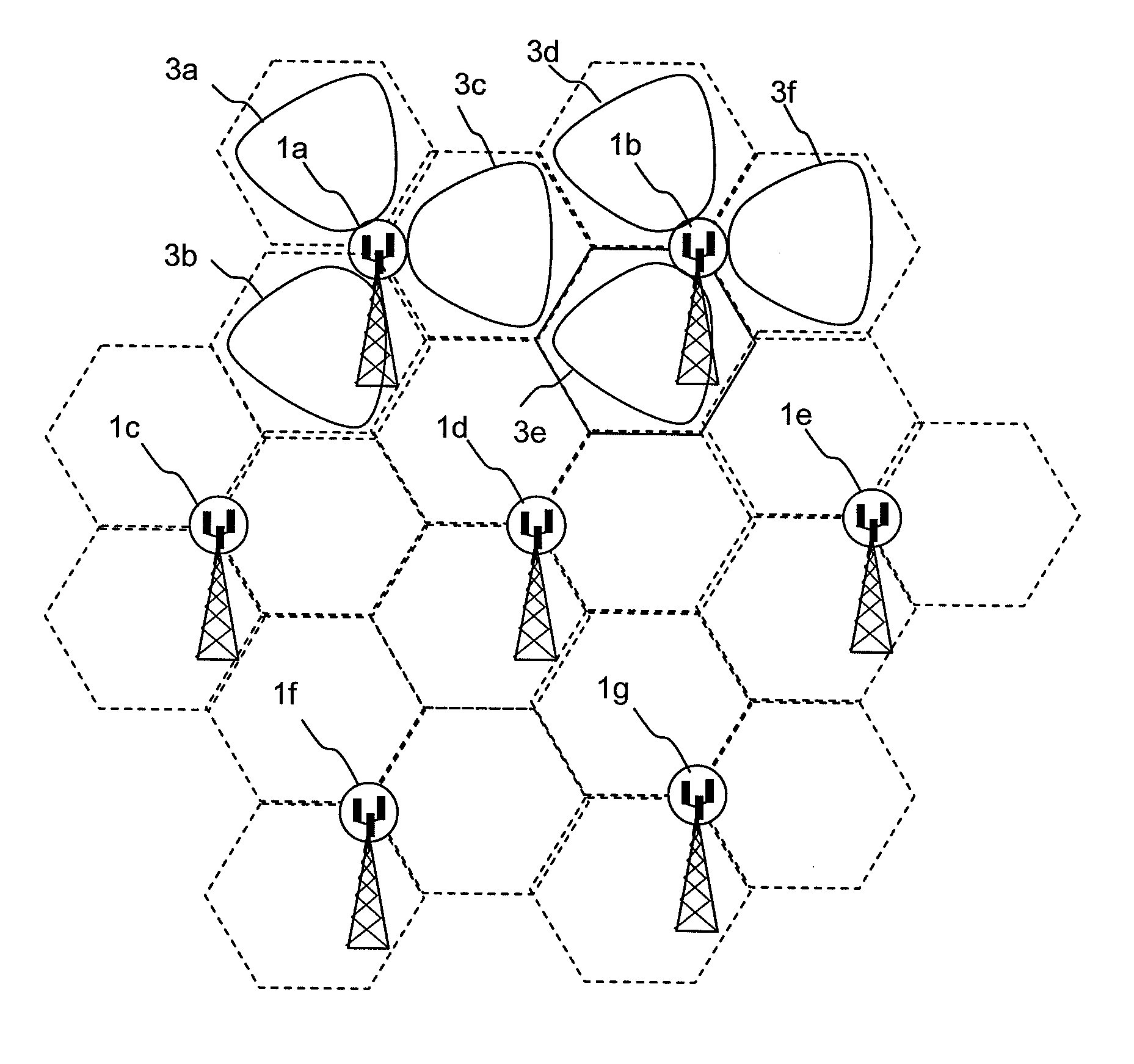
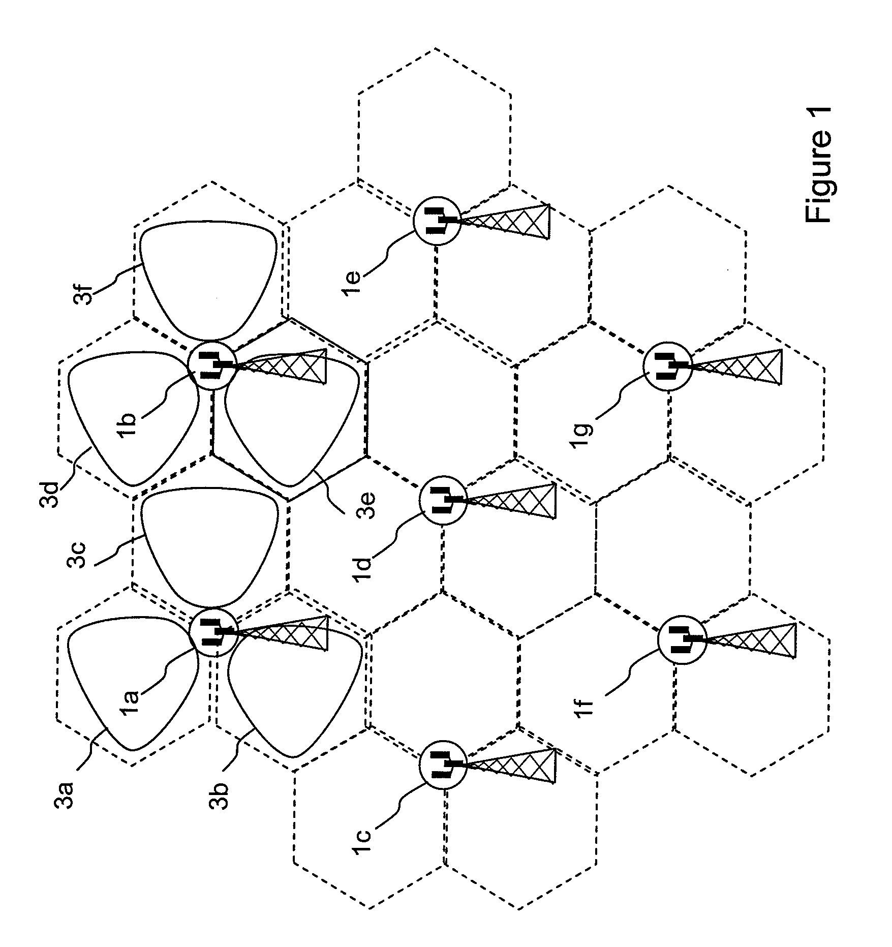
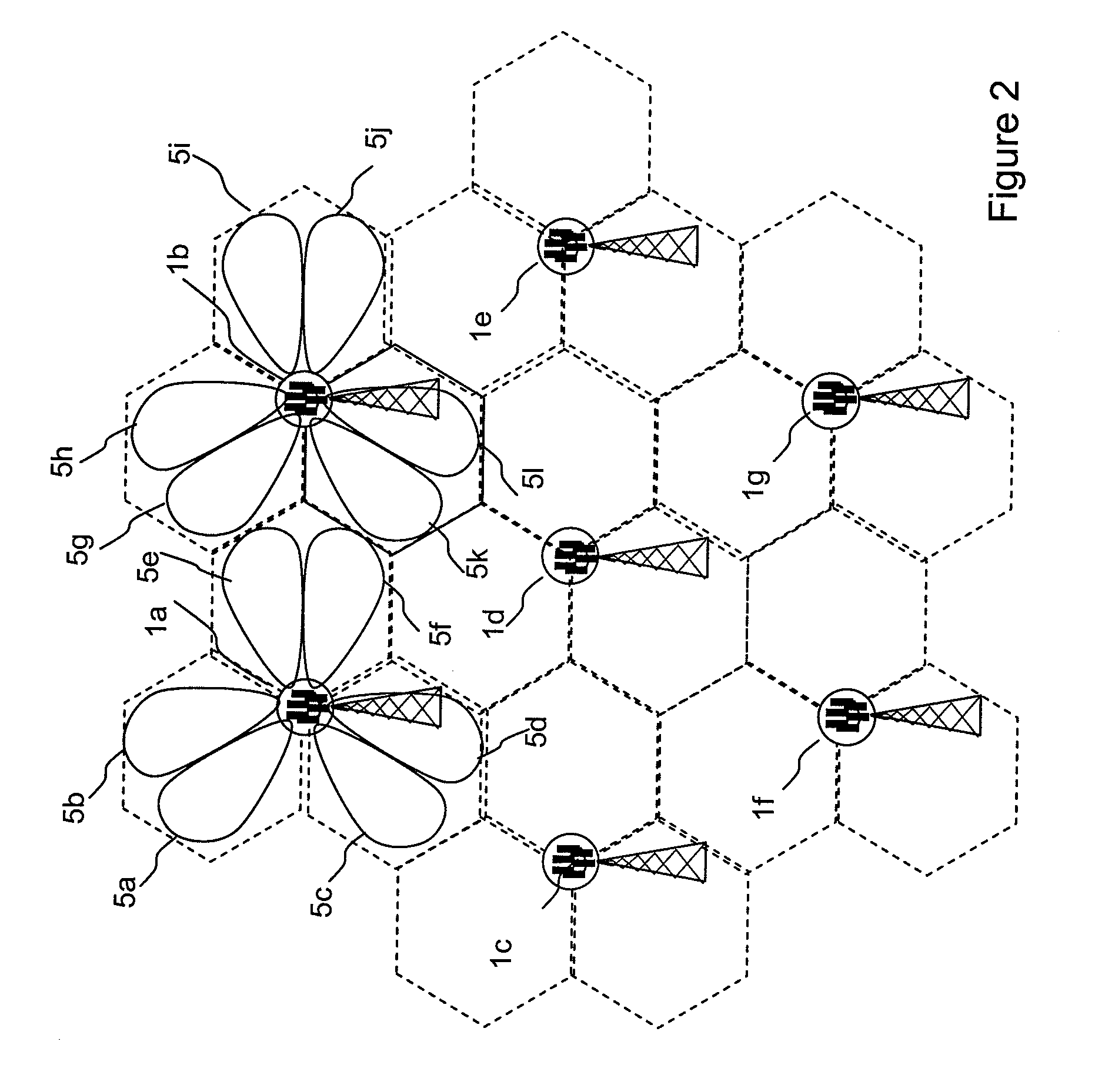
[0044]In general, the present invention is directed to methods and apparatus that enhance the capacity of wireless communications between a base station and remote stations by the implementation of space division multiplexing. The invention will be described in the context of a cellular wireless system, but it is to be understood that this example is chosen for illustration only and that other applications of the invention are possible.

[0045]FIG. 3 illustrates a first embodiment of the invention, which relates to space division multiplexing. In the first embodiment, two antennas 11a, 11b and a hybrid combiner 21 produce two antenna beams with different radiation patterns that are connected to respective radio transceivers 27a, 27b. The beam that is produced at the sum port 23 of the hybrid combiner 21 will be referred to as the sum beam, and the beam that is produced at the difference port 25 of the hybrid combiner 21 will be referred to as the difference beam. The radiation pattern...


PUM


Abstract

Embodiments of the invention relate to beamforming antennas such as can be used in space division multiplexing systems. Space division multiplexing can be used to increase data capacity in wireless networks by enabling different base stations to transmit signals within the same frequency band. Each antenna beam can potentially be used to establish a communication link within an area of wireless coverage, and other communication links established on other antenna beams then represent interference to that user. In order to reduce interference, narrow beamwidths are desirable. These are typically achieved by increasing the aperture of the antenna in the azimuth plane, and in arrangements that require finely divided angular sectors, a greater number of antennas will be required to give three hundred and sixty degree coverage. As a result, there is potentially a large increase in the total surface area of antennas which is undesirable, as it leads to increased wind loading of an antenna tower. Embodiments of the invention provide an arrangement in which data are transmitted from a first transmitter to a first receiver using a first antenna beam, and data are transmitted from a second transmitter to a second receiver using a second antenna beam. The first antenna beam is formed by splitting the signal from the first transmitter into two parts with a first phase relationship between the parts, each part being connected to an antenna. A second antenna beam is formed by splitting the signal from the second transmitter into two parts with a second phase relationship between the parts, each part being connected to one of the two antennas. An advantage of embodiments of the invention is that data can be transmitted from different transmitters at the same frequency without interference, while presenting a smaller antenna aperture than is required with conventional systems.

Description

FIELD OF THE INVENTION [0001]The present invention relates generally to antennas for wireless data communications networks, and more specifically to beamforming antenna systems.BACKGROUND OF THE INVENTION [0002]Modem wireless communications systems place great demands on the antennas used to transmit and receive signals, especially at cellular wireless base stations. Antennas are required to produce a carefully tailored radiation pattern with a defined beamwidth in azimuth, so that, for example, the wireless cellular coverage area has a controlled overlap with the coverage area of other antennas.[0003]In addition to a defined azimuth beam, such antennas are also required to produce a precisely defined beam pattern in elevation; in fact the elevation beam is generally required to be narrower than the width of the azimuth beam.[0004]It is conventional to construct such antennas as an array of antenna elements so as to form the required beam patterns. Such arrays require a feed network...

Claims


Application Information

Patent Timeline
IPC IPC(8): H04B7/185
CPCH04B7/0452H04B7/10H04B7/086H04B7/0617
Inventor ADAMS, DAVID
Owner APPLE INC
Why Eureka
Try Eureka