X-ray analyzer and x-ray analysis method

a technology of x-ray analyzer and x-ray analysis, which is applied in the direction of instruments, radiation measurement, measurement devices, etc., to achieve the effects of avoiding the collision of samples and apparatuses, safe and reliable measurement, and optimizing analysis performan

Active Publication Date: 2010-02-25
HITACHI HIGH TECH SCI CORP
View PDF7 Cites 30 Cited by
  • Summary
  • Abstract
  • Description
  • Claims
  • Application Information

AI Technical Summary

Benefits of technology

[0022]That is, in the X-ray analyzer and the X-ray analysis method according to the aspects of the invention, the control unit adjusts the distance between the sample and the radiation source and the distance between the sample and the X-ray detector by controlling the moving mechanism on the basis of the measured maximum height of the sample. This restricts the range of movement made by the moving mechanism so that collision of the sample and the apparatus can be avoided. Accordingly, optimization of analysis performance according to an uneven state of a sample can be realized by acquiring information on the height of the sample.
[0023]As a result, an operator can safely perform the measurement without being concerned about collision.

Problems solved by technology

However, as shown in FIG. 4, in the case of an uneven sample S like a mounting board or in the case of a sample having a thin pin shaped or thin line shaped protruding portion (for example, a thin metal wire based on wire bonding) which is difficult to be viewed by an observation system, such as an image processing device, or by visual observation, there has been a possibility that an X-ray tube 2 or an X-ray detector 3 is brought too close to the sample S on a sample stage 1 at the time of X-ray irradiation distance adjustment and as a result, the X-ray tube 2 or the X-ray detector 3 may collide with the sample S accidentally.

Method used


Image

  • X-ray analyzer and x-ray analysis method
  • X-ray analyzer and x-ray analysis method
  • X-ray analyzer and x-ray analysis method

Examples


Embodiment Construction

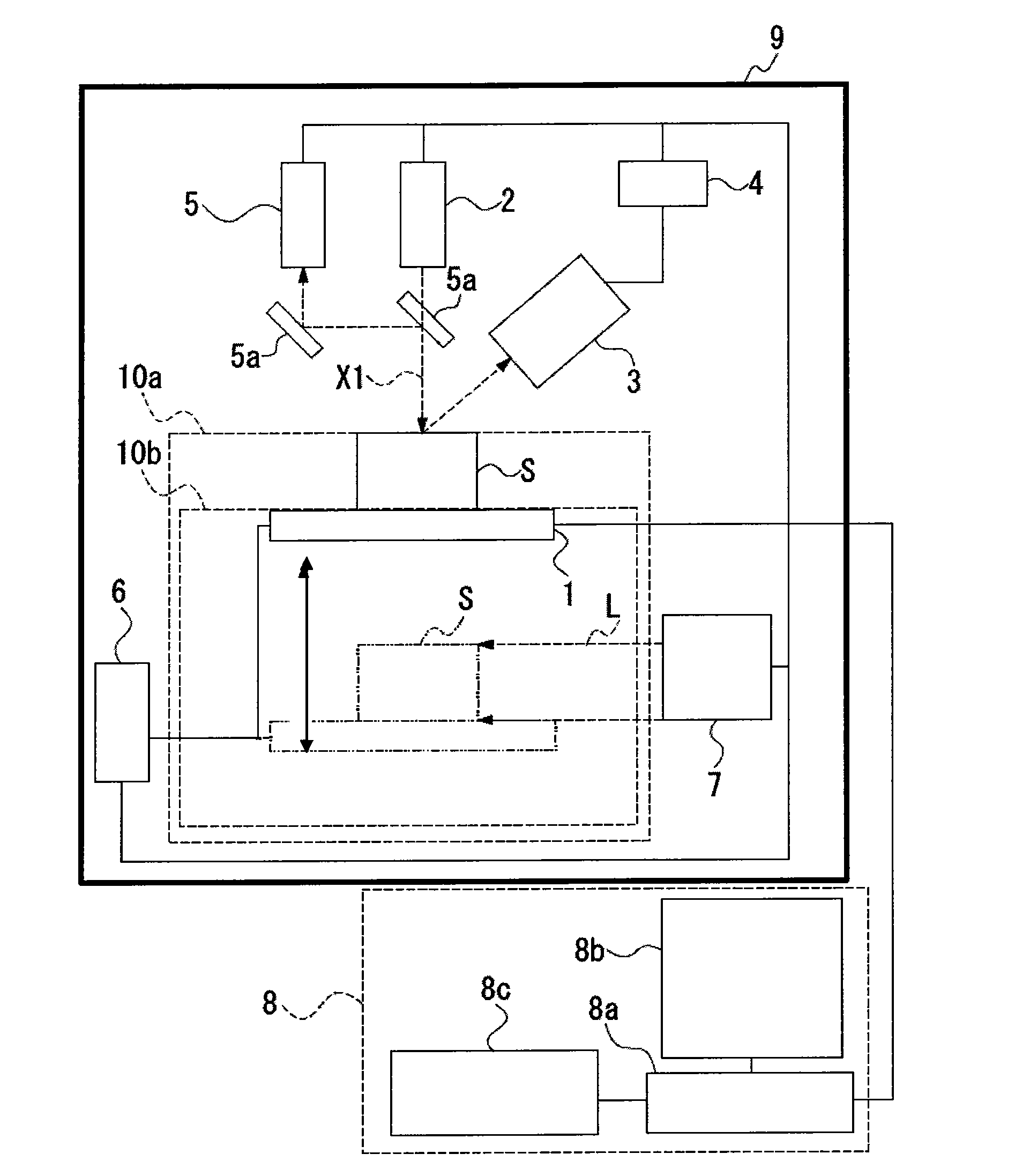
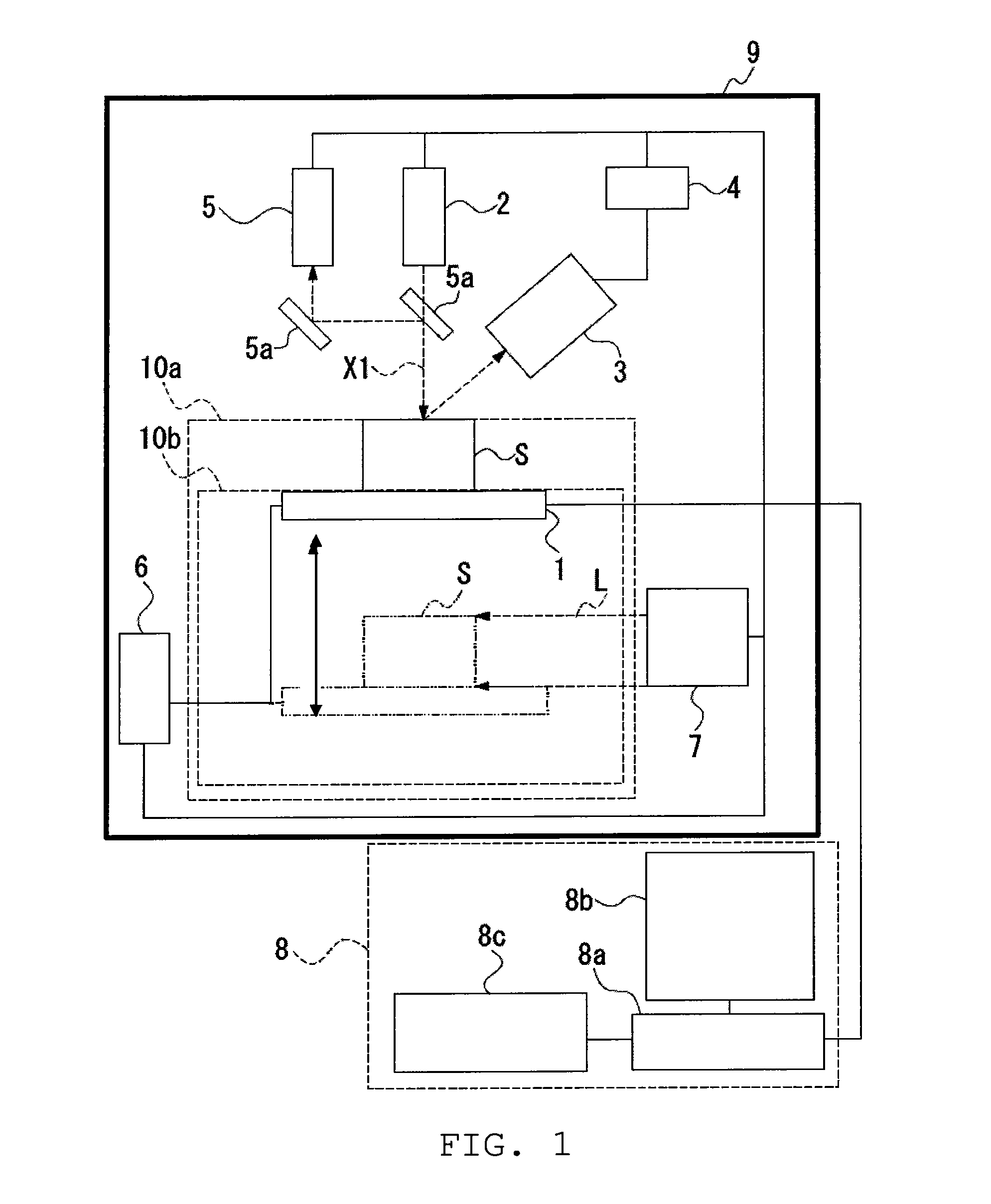
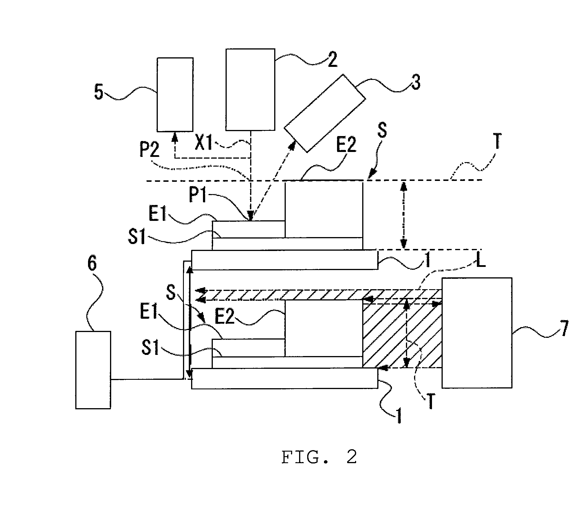
[0030]Hereinafter, an embodiment of X-ray analyzer and X-ray analysis method according to the invention will be described with reference to FIGS. 1 to 3. Incidentally, in each drawing used for the following description, the scale of each member may be suitably adjusted in order to have a recognizable size as is required.

[0031]The X-ray analyzer of the present embodiment is an energy dispersive fluorescent X-ray analyzer, for example. As shown in FIGS. 1 and 2, the X-ray analyzer of the present embodiment includes: a sample stage (moving mechanism) 1 on which a sample S is placed and which is movable; an X-ray tube (radiation source) 2 which irradiates a primary X-ray (radial ray) X1 to an arbitrary irradiation point P1 on the sample S; an X-ray detector 3 which detects a characteristic X-ray and a scattered X-ray emitted from the sample S and outputs a signal including energy information on the characteristic X-ray and scattered X-ray; an analyzer 4 which is connected to the X-ray d...


PUM

PropertyMeasurementUnit
energyaaaaaaaaaa
height measuringaaaaaaaaaa
heightaaaaaaaaaa

Abstract

An X-ray tube which irradiates a primary X-ray to an irradiation point on a sample, an X-ray detector which detects a characteristic X-ray and a scattered X-ray emitted from the sample and outputs a signal including energy information on the characteristic X-ray and scattered X-ray, an analyzer which analyzes the signal, a sample stage on which the sample is placed, a moving mechanism which moves the sample on the sample stage, the X-ray tube, and the X-ray detector relative to each other, a height measuring mechanism which measures a maximum height of the sample, and a control unit which adjusts the distance between the sample and the X-ray tube and the distance between the sample and the X-ray detector by controlling the moving mechanism on the basis of the measured maximum height of the sample, are included.

Description

RELATED APPLICATIONS[0001]This application claims priority under 35 U.S.C. §119 to Japanese Patent Application Nos. JP2008-214715 filed on Aug. 22, 2008 and JP2008-277732 filed on Oct. 29, 2008, the entire contents of which are hereby incorporated by reference.BACKGROUND OF THE INVENTION[0002]1. Field of the Invention[0003]The present invention relates to an X-ray analyzer and an X-ray analysis method suitable for X-ray mapping analysis of a sample surface using fluorescent X-ray analysis and the like.[0004]2. Description of the Related Art[0005]In the fluorescent X-ray analysis, an X-ray emitted from an X-ray source is irradiated onto a sample, a fluorescent X-ray which is a characteristic X-ray emitted from the sample is detected by an X-ray detector, and a spectrum is acquired from the energy and a qualitative analysis or quantitative analysis of the sample is performed. Fluorescent X-ray analysis is widely used in process management, quality management, and the like since a samp...

Claims


Application Information

Patent Timeline
Patent Type & Authority Applications(United States)
IPC IPC(8): G01N23/223
CPCG01N2223/076G01N23/223
Inventor SAKAI, NORIAKITAKAHARA, TOSHIYUKIMATOBA, YOSHIKI
Owner HITACHI HIGH TECH SCI CORP
Why Eureka
Try Eureka