High-pressure fluidized bed reactor for preparing granular polycrystalline silicon

a technology of fluidized bed reactor and granular polycrystalline silicon, which is applied in the direction of gas-gas reaction process, furnace, instruments, etc., can solve the problems of low deposition efficiency and high electrical energy consumption, the bell-jar type reactor, and the fundamental electric resistance heating system cannot be continuously operated, etc., to achieve the effect of reducing the fluidity of the reactor, reducing the fluidity, and reducing the fluidity

Active Publication Date: 2010-02-25
KOREA RES INST OF CHEM TECH
View PDF9 Cites 46 Cited by
  • Summary
  • Abstract
  • Description
  • Claims
  • Application Information

AI Technical Summary

Benefits of technology

[0038]Sealing means 41a, 41b may be used for the reactor shell 1 to safely hold the reactor tube 2. The sealing means are preferred to be stable at a temperature of above 200° C. and may be selected from organic polymer, graphite, silica, ceramic, metal or their combination. However, considering the vibration and thermal expansion during reactor operation, the sealing means 41a, 41b may be installed less firmly to lower the possibility of cracking of the reactor tube 2 in the course of assembly, operation and disassembly.
[0142]Therefore, when the equalizing line 23 is used as the pressure-difference controlling means, a pressure equalizing means, which can decrease or prevent the possible interexchange of gas and impurity components between two zones 4, 5, may be further added to the equalizing line 23. The pressure equalizing means may comprise at least one means selected from a check valve, a pressure equalizing valve, a 3-way valve, a filter for separating particles, a damping container, a packed bed, a piston, an assistant control fluid, and a pressure compensation device using separation membrane, which, respectively, is able to prevent the possible interexchange of gas and impurity components without deteriorating the effect of pressure equalization.

Problems solved by technology

However, the bell-jar type reactor, which consists fundamentally of the electric resistance heating system, cannot be operated continuously due to inevitable limit in extending the maximum rod diameter achievable.
This reactor is also known to have serious problems of low deposition efficiency and high electrical energy consumption because of limited silicon surfaces and high heat loss.
Here, smaller silicon particles, i.e., seed crystals become bigger in size due to continuous silicon deposition or the agglomeration of silicon particles, thereby losing fluidity and ultimately moving downwards.
Unlike conventional fluidized bed reactors, serious limitations are encountered in material selection of the components of the fluidized bed reactor for preparing polycrystalline silicon.
The reactor wall is weak in physical stability because it is always in contact with silicon particles fluidizing at high temperatures, and is subject to the irregular vibration and severe shear stress caused by the fluidized bed of the particles.
However, it is very difficult to select an appropriate material among the high-purity non-metallic inorganic materials that are capable of enduring a relatively high pressure condition, because metallic material is not appropriate because of high reaction temperature and chemical properties of the reaction gas.
For this reason, the fluidized bed reactor for manufacture of polycrystalline silicon inevitably has a complicated structure.
However, this patent still has a problem of a complex structure of the reactor and fails to disclose how to increase the reaction pressure inside the quartz reactor tube.
However, this patent still has problems that the inner pressure cannot be increased beyond atmospheric pressure and the microwave supplying means should be combined with the reactor shell, thus failing to suggest how to overcome the mechanical weakness of the reactor tube that is anticipated at high-pressure reaction.

Method used


Image

  • High-pressure fluidized bed reactor for preparing granular polycrystalline silicon
  • High-pressure fluidized bed reactor for preparing granular polycrystalline silicon

Examples


example 1

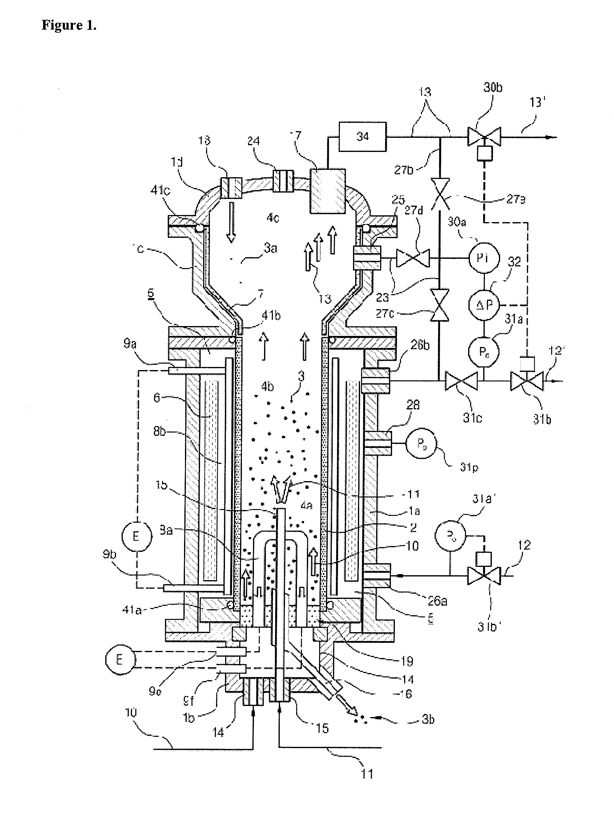
[0167]Hereunder is provided a description of one embodiment where the inner pressure (Pi) and the outer pressure (Po) are independently controlled at predetermined values, Pi* and Po*, respectively, and the difference between the values of the inner pressure and the outer pressure is thereby maintained within the range of 0 to 1 bar.

[0168]As illustrated in FIGS. 1 and 2, an inner pressure controlling means 30 may be constituted by interconnecting a first pressure control valve 30b with a gas outlet means 17 through an off-gas treating means 34 for removing fine silicon particles, which are interconnected with each other by a connecting pipe. The pressure of the upper part of the inner zone 4 may be controlled at a predetermined value, Pi*, by using the first pressure control valve 30b which behaves as an element of a pressure-difference controlling means.

[0169]Meanwhile, as illustrated in FIG. 1, an outer pressure controlling means 31 may be constituted by interconnecting an inert g...

example 2

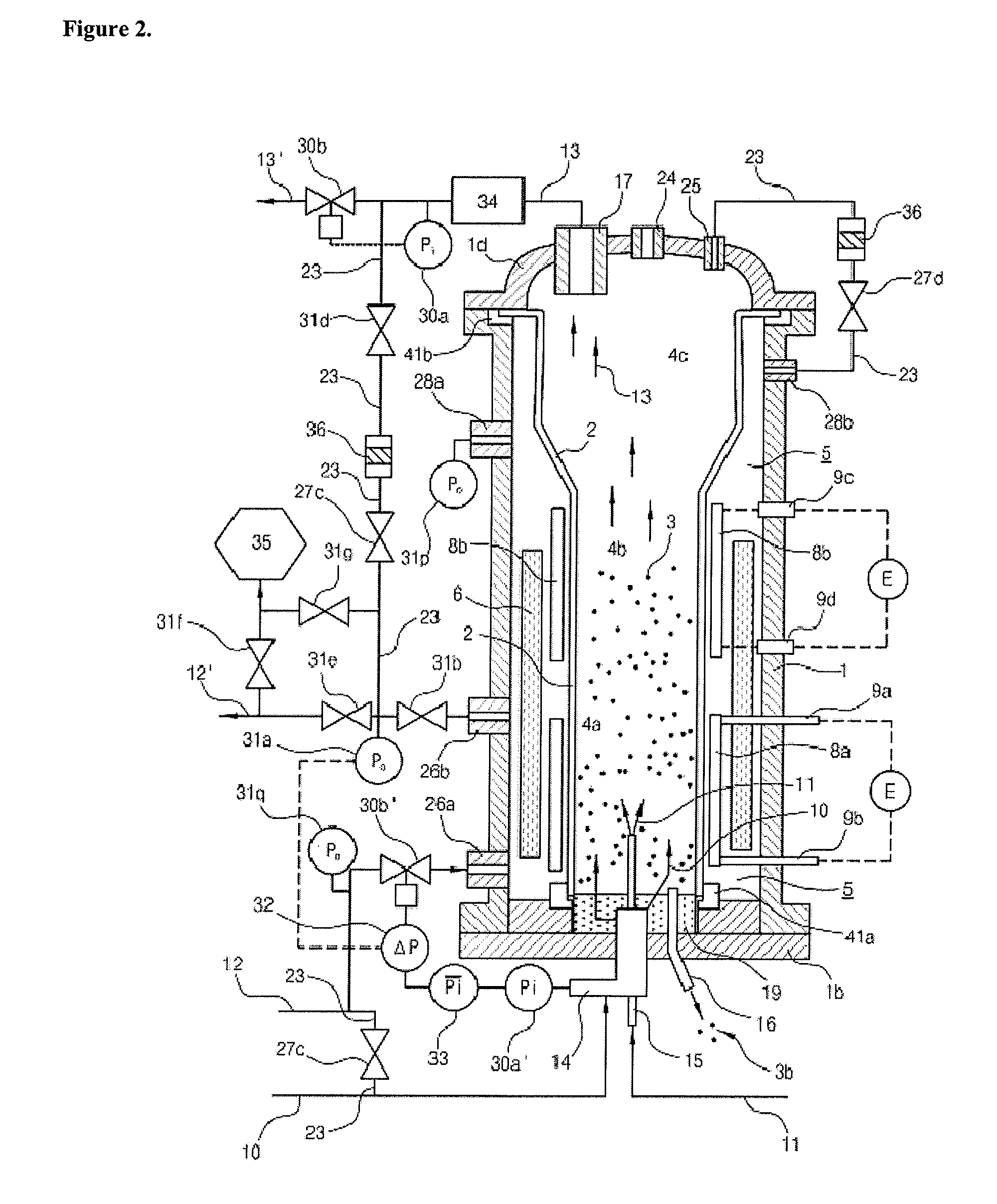
[0174]Hereunder is provided a description of another embodiment where the inner pressure (Pi) and the outer pressure (Po) are independently controlled at the predetermined values, Pi* and Po*, respectively, and the difference between the values of the inner pressure and the outer pressure is thereby maintained within the range of 0 to 1 bar.

[0175]As illustrated in FIGS. 1 and 2, an inner pressure controlling means 30 may be constituted by interconnecting a first pressure control valve 30b with the gas outlet means 17 through the off-gas treating means 34 for removing fine silicon particles, which are interconnected with each other by a connecting pipe. The pressure of the upper part of the inner zone 4 may be controlled at a predetermined value, Pi*, by using the first pressure control valve 30b which behaves as an element of a pressure-difference controlling means.

[0176]Meanwhile, as illustrated in FIG. 1, an outer pressure controlling means 31 may be constituted by interconnecting...

example 3

[0182]Hereunder is provided a description of one embodiment where the inner pressure (Pi) is controlled according to the change of the outer pressure (Po), and the difference between the values of the inner pressure and the outer pressure is thereby maintained within the range of 0 to 1 bar.

[0183]As illustrated in FIGS. 1 and 2, a gas outlet means 17, an off-gas treating means 34 for removing fine silicon particles and a first pressure control valve 30b are interconnected with each other by a connecting pipe. Then an inner pressure controlling means 30 may be constituted by interconnecting the connecting pipe with an on / off valve 27e and a pressure-difference gauge 32.

[0184]Meanwhile, as illustrated in FIG. 1, an outer pressure controlling means 31 may be constituted by interconnecting an inert gas connecting means 26b and a pressure-difference gauge 32, which are interconnected with each other by the connecting pipe. Here an inert gas 12 may be supplied to the outer zone through an...


PUM

PropertyMeasurementUnit
pressureaaaaaaaaaa
pressureaaaaaaaaaa
sizeaaaaaaaaaa

Abstract

The present invention relates to a high-pressure fluidized bed reactor for preparing granular polycrystalline silicon, comprising (a) a reactor tube, (b) a reactor shell encompassing the reactor tube, (c) an inner zone formed within the reactor tube, where a silicon particle bed is formed and silicon deposition occurs, and an outer zone formed in between the reactor shell and the reactor tube, which is maintained under the inert gas atmosphere, and (d) a controlling means to keep the difference between pressures in the inner zone and the outer zone being maintained within the range of 0 to 1 bar, thereby enabling to maintain physical stability of the reactor tube and efficiently prepare granular polycrystalline silicon even at relatively high reaction pressure.

Description

CROSS-REFERENCE TO RELATED APPLICATIONS[0001]This application is a continuation of U.S. patent application Ser. No. 12 / 093,513 filed May 13, 2008 entitled “High-Pressure Fluidized Bed Reactor for Preparing Granular Polycrystalline Silicon” which is a 371 application of PCT / KR2007 / 000657 filed Feb. 7, 2007 and which claims priority benefits of Korean Application Number 10-2006-0011493 filed Feb. 7, 2006, the disclosures of all applications of which are incorporated herein by reference.TECHNICAL FIELD[0002]The present invention relates to a high-pressure fluidized bed reactor for preparing granular polycrystalline silicon that enables to maintain long-term stability of the reactor tube and efficiently prepare granular polycrystalline silicon even at relatively high reaction pressure.BACKGROUND ART[0003]Generally, high-purity polycrystalline silicon is used as a basic material for manufacturing semiconductor devices or solar cells. The polycrystalline silicon is prepared by thermal dec...

Claims


Application Information

Patent Timeline
Patent Type & Authority Applications(United States)
IPC IPC(8): G05D16/00B01J8/18
CPCB01J3/046B01J8/1827B01J8/1836C01B33/03B01J2208/00407C01B33/027C01B33/029B01J2208/00398A47J37/0682A47J37/0786
Inventor KIM, HEE YOUNGYOON, KYUNG KOOPARK, YONG KICHOI, WON CHOON
Owner KOREA RES INST OF CHEM TECH
Why Eureka
Try Eureka