Method and device for synchronizing two bus systems and arrangement composed to two bus systems

a bus system and bus system technology, applied in the direction of synchronization signal speed/phase control, data switching network, instruments, etc., can solve the problems of high demands on the planning pool, high load on at least one station processor, and certain dependence on software latencies

Active Publication Date: 2010-02-25
ROBERT BOSCH GMBH
View PDF15 Cites 51 Cited by
  • Summary
  • Abstract
  • Description
  • Claims
  • Application Information

AI Technical Summary

Benefits of technology

[0009]Example embodiments of the present invention provide a method for synchronizing a plurality of autonomous protocol controllers as communications modules, and hence the bus systems associated therewith, with a common time base, without interventions of a station processor being necessary. That is to say, synchronization of the bus systems is to be performed without direct supervision by the processor used and independently of software latencies.

Problems solved by technology

In the case of the purely time-triggered approach, therefore, high demands are made on the planning pool.
A disadvantage with such a method, however, is that intervention of the host controller or processor always takes place, and therefore, in the case of synchronizing a plurality of networks or bus systems, a high load is placed on at least one station processor and a certain dependence upon software latencies arises.

Method used


Image

  • Method and device for synchronizing two bus systems and arrangement composed to two bus systems
  • Method and device for synchronizing two bus systems and arrangement composed to two bus systems
  • Method and device for synchronizing two bus systems and arrangement composed to two bus systems

Examples


Embodiment Construction

[0027]The present invention will now be described in detail below with reference to exemplary embodiments.

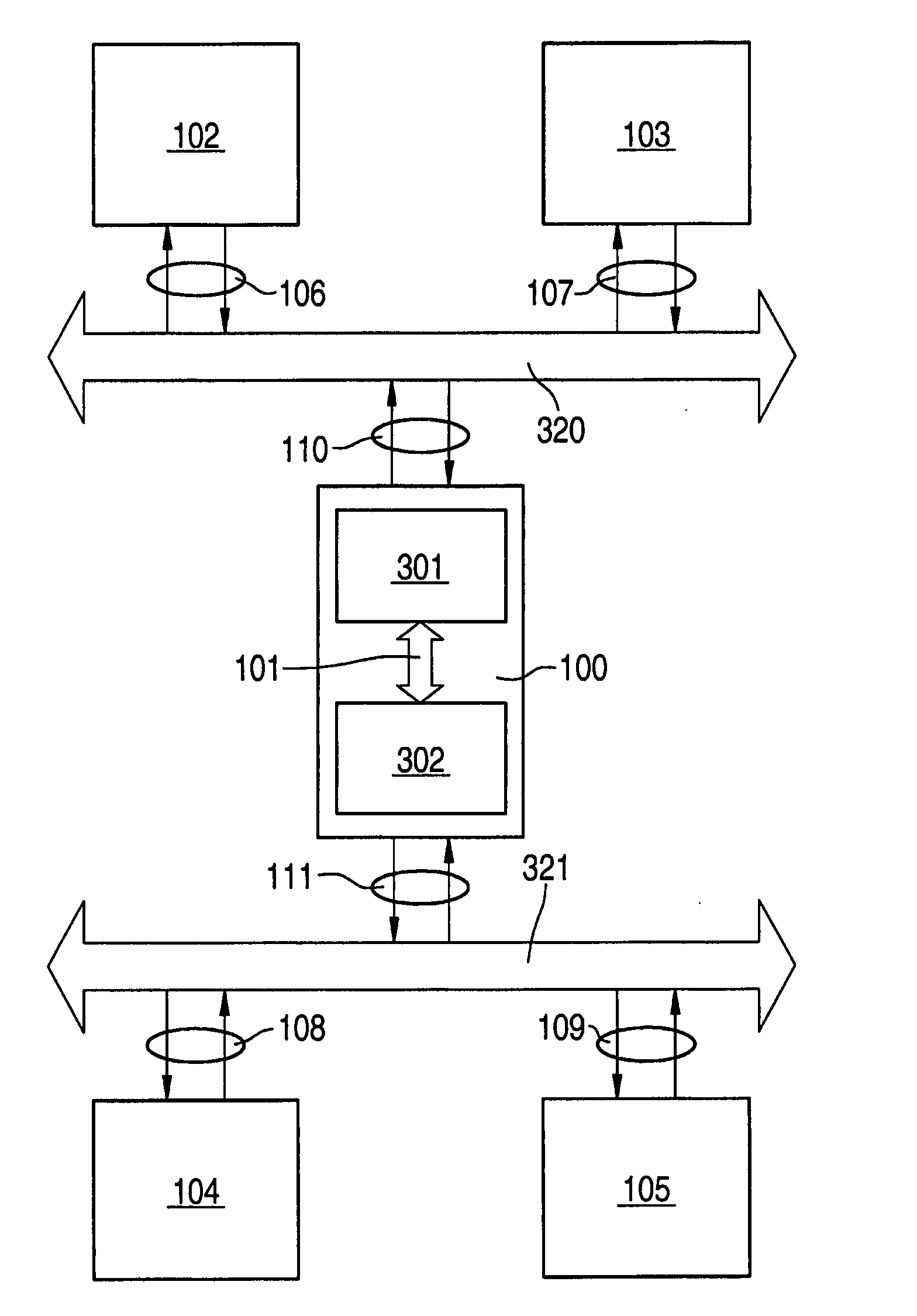
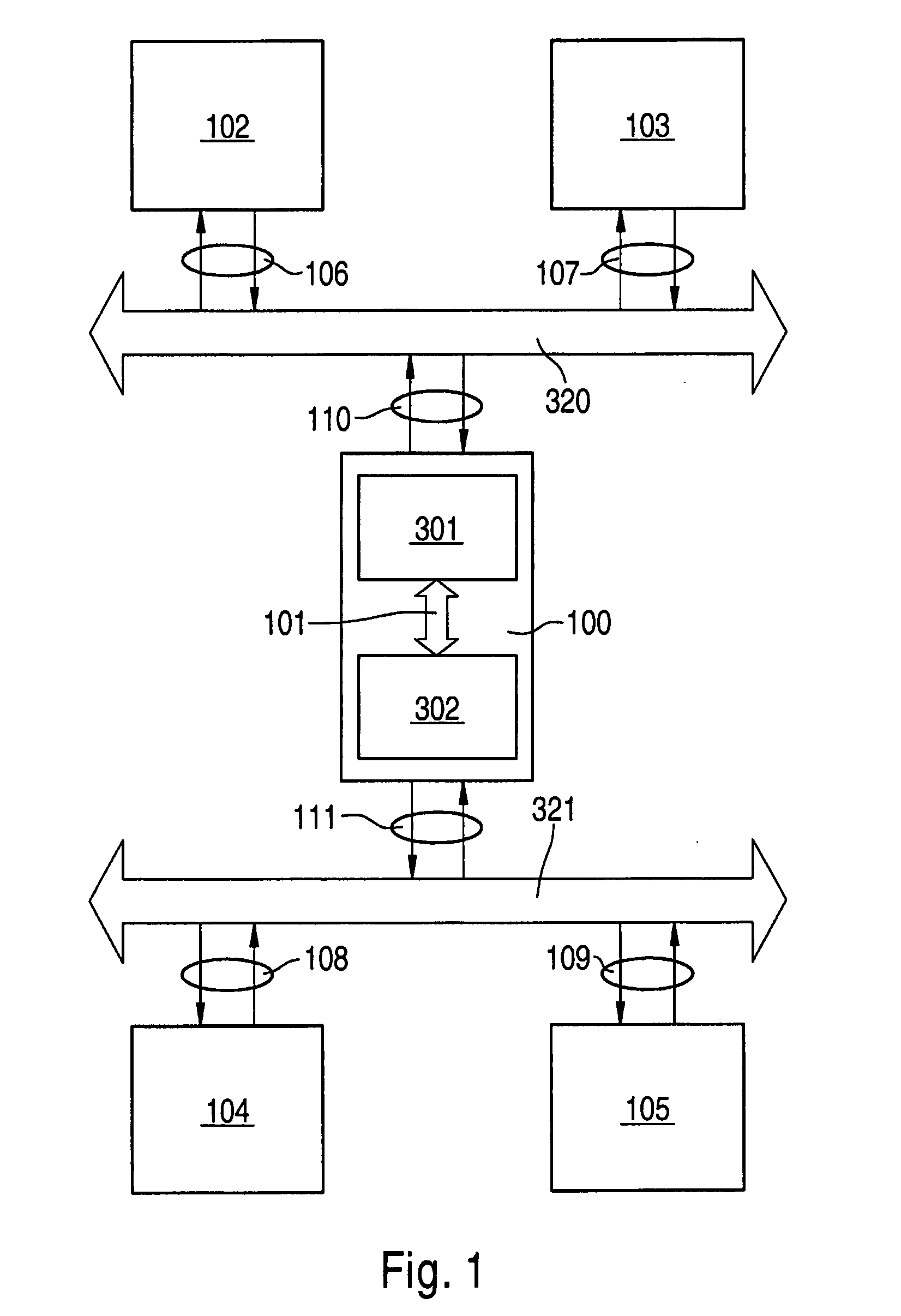
[0028]FIG. 1 shows an arrangement composed of two bus systems 320 and 321 and a device forming a gateway between the bus systems. Bus system 320 has stations or nodes 102 and 103 which are linked to the bus system via bidirectional connections 106 and 107, respectively. Also illustrated is a second bus system 321, which has stations 104 and 105 and is connected to those stations via bidirectional interfaces 108 and 109.

[0029]100 denotes a gateway station through which bus systems 320 and 321 are connected to each other. This is done with bus system 320 via bidirectional interface 110 and with bus system 321 via bidirectional interface 111. 301 and 302 denote communications modules, first communications module 301 being coupled to bus system 320, that is to say being used for that bus system, and second communications module 302 being coupled to bus system 321 and thus being resp...


PUM


Abstract

A device for synchronizing at least two bus systems, having a first communications module for a first bus system and a second communications module for a second bus system, wherein in the first communications module first trigger information is present by which a trigger signal is triggered in the first bus system, characterized in that the device is configured in such a manner that the first and second communications modules are connected to each other and the first trigger information is transmitted to the second communications module, and the second communications module is configured in such a manner that a time information value is determined from the first trigger information and that time information value is compared with a second time mark of the second bus system, a time difference being determined and the next reference message being triggered in the second bus system in dependence upon the second time mark and the time difference.

Description

FIELD OF THE INVENTION[0001]The present invention relates to a method and a device for synchronizing two bus systems and to a corresponding arrangement composed of two bus systems in which time control is effected by reference messages.BACKGROUND INFORMATION[0002]A reference message of that kind for producing basic cycles in the context of time-controlled communication on a bus system is used, for example, in the case of FlexRay or also in the case of TTCAN. Such bus systems are necessary, since the networking of control units, sensors and actuators has increased dramatically in recent years not only in modern motor vehicle manufacturing and in engineering, especially in the machine tool sector, but also in automation technology. It is possible in these cases to obtain synergetic effects by distributing functions among several control units. Communication between various stations of such distributed systems is increasingly taking place, therefore, via a bus system or via a plurality...

Claims


Application Information

Patent Timeline
Patent Type & Authority Applications(United States)
IPC IPC(8): G06F13/00
CPCH04J3/0655H04L12/4625H04L7/08
Inventor HARTWICH, FLORIANTAUBE, JAN
Owner ROBERT BOSCH GMBH
Why Eureka
Try Eureka